 In the process of hardware development and testing,oscilloscopes are indispensable powerful tools, but many people overlook their good partner —oscilloscopeprobes. If the probe is not selected correctly, the measured signal may be distorted, deformed, or even mislead the debugging party! Even more exaggerated, some high-end probes can sell for hundreds or even thousands of dollars. Why are they so expensive? Because they directly determine your measurement accuracy! (Refer to the Tektronix official website)
Today, let’s discuss the6 common pitfalls when selecting oscilloscope probes, and see if you’ve fallen into any of them?
011
Not understanding key technical specifications
When selecting a probe, you cannot just look at the bandwidth! A higher bandwidth can capture more signal details, but it can also introduce more noise and may increase costs and development difficulty.
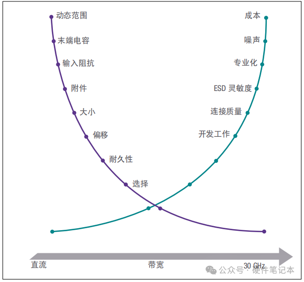
Other key specifications include:
-
dynamics range: The range of signal amplitudes that the probe can measure.
-
terminal capacitance: The smaller the capacitance, the better the high-frequency performance.
-
input impedance: Affects signal loading effects (the higher the impedance, the better).
-
noise and cost: The higher the bandwidth, the greater the noise, and the more expensive the price.
So, don’t blindly pursue high bandwidth; you can study relevant technical documentation more.
021
Incorrect bandwidth selection can lead to signal detail loss
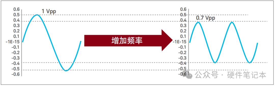
If the bandwidth is too low, signal details are easily lost; if the bandwidth is too high, it will introduce unnecessary noise and waste money. The bandwidth of the probe is essentially the -3dB point.
When using a 1:1 probe to measure a 1 Vpp sine wave, the low-frequency output equals the actual signal. However, as the frequency increases, when the oscilloscope displays an amplitude of 0.7 Vpp (i.e., the 3dB point of the input signal), it indicates that the probe output has attenuated by 3 dB relative to the nominal value.
The calculation method for signal bandwidth BW can refer to the following:
If we measure the 10% and 90% thresholds, then the signal bandwidth:
BW = rise time / 0.35;
If we measure the 20% and 80% thresholds, then the signal bandwidth:
BW = rise time / 0.22.
Then we can calculate the probe bandwidth:
The probe bandwidth should be 3 times higher than the fastest sine wave frequency in the analog signal and 5 times faster than the highest digital clock rate. Follow the public account: Hardware Notebook
031
Ignoring the loading effect of the probe
Once the probe is connected to the circuit, it becomes part of the circuit, forming a load, which also affects the signal. This is unavoidable; we can only try to minimize the loading effect. Follow the public account: Hardware Notebook
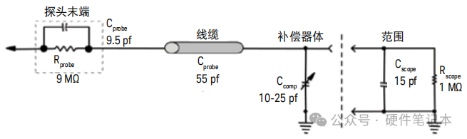
The following figure shows the basic model of a passive probe, where resistor R is the load, and capacitor C is the result of the capacitive components and parasitic capacitance.
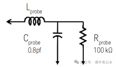
As shown in the figure, the impedance of the capacitor is inversely proportional to the frequency. As the frequency increases, the capacitor becomes easier to ground than the resistor.
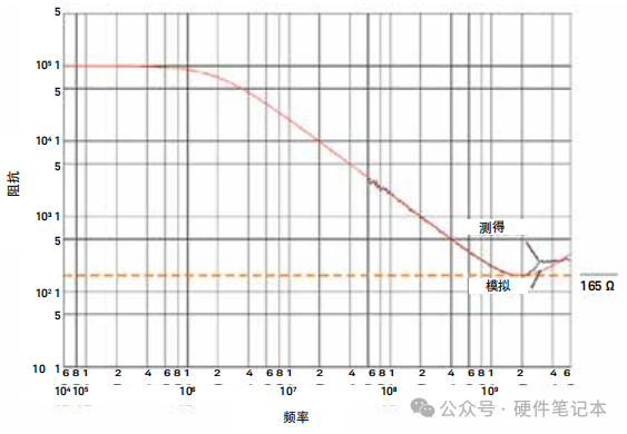
The loading effect of active probes is much smaller than that of passive probes because passive probes are made only of resistive and capacitive components. Moreover, passive probes have a large loading effect (for example, a 10MΩ resistor but large capacitance, leading to a sharp drop in impedance at high frequencies), while active probes have a small loading effect (1MΩ resistor but small capacitance, better high-frequency performance).
It is recommended to use active probes for high-frequency signals and passive probes for low-frequency signals.
041
Active or passive? Can’t tell the difference
In general, passive probes are cheap, durable, and suitable for low-frequency small signals (such as 1:1 attenuation for measuring small voltages), while active probes are expensive, high-precision, and suitable for high-frequency or high-precision requirements (such as measuring high-speed digital signals).
Comparing capacitance, as shown in the figure, when we choose oscilloscope probes, we often focus on resistance, believing that a passive probe with a 10MΩ resistance is better than an active probe with a 1MΩ resistance. However, after 10kHz, as the frequency increases, their impedance appears to differ significantly.
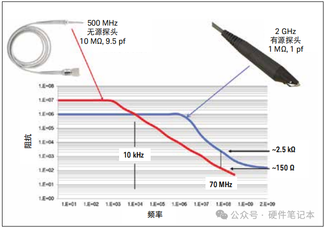
Therefore, at high frequencies, the capacitive loading effect is more important than the resistive loading effect! Active probes have smaller capacitance, making their advantages more apparent.
051
Incorrect connection method can halve the bandwidth!
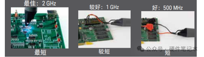
The shorter the connection, the higher the bandwidth, for example, a 2GHz probe with long leads may only have an actual bandwidth of 500MHz.
The more accessories, the greater the loading effect, so try to use the shortest connection method.
Example: N2796A 2 GHz active probe
061
Incorrect attenuation ratio selection can lead to signal “clipping”
The attenuation ratio of oscilloscope probes is adjustable. Its principle is that the attenuation ratio is a voltage divider circuit, for example, a 10:1 probe uses a 9MΩ + 1MΩ resistor divider, reducing the signal entering the oscilloscope by a factor of 10.
1:1 probe: Suitable for small signals (low noise but high load).
10:1 probe: Suitable for high voltages (protects the oscilloscope but has slightly higher noise).
Incorrect demonstration is using a 1:1 probe to measure high voltage, which will cause the signal to be clipped!