
1
CAN Bus System
The full English name of the CAN bus is Controller Area Network, which is one of the most widely used buses in automobiles. Pure electric vehicles generally have seven CAN bus systems, which are named differently by various automobile manufacturers, commonly referred to as: New Energy Bus (EVBUS), Fast Charging Bus (FCBUS), Internal Battery Bus (BBUS), Remote Monitoring Bus (TBUS), Chassis Bus (CBUS), Comfort Bus (EBUS), and Infotainment Bus (IBUS). The first three bus systems are unique to electric vehicles, while the last four bus systems are derived from fuel vehicles. The full English name of the LIN bus is Local Interconnect Network, which is a low-cost communication network that complements the CAN network, allowing the main control unit to connect to sub-control units via the LIN bus.
The number of CAN subsystems and the combination of control units designed for different electric vehicle models vary. The CAN network for a certain model is shown in Figure 1, which includes the Power CAN system, Chassis CAN system, and Body CAN system. The Power CAN system and Chassis CAN system are high-speed CAN, with a transmission rate of 500kbit/s; the Body CAN system is medium-speed CAN, with a transmission rate of 125kbit/s.

Figure 1 CAN Network
1) The Power CAN system coordinates communication among the MCU (Motor Control Unit), BMS (Battery Management System), DC/DC (Direct Current Converter), and Compressor Controller. The BMS has a slow charging CAN bus with the OBC (On-Board Charger).
2) The Chassis CAN system coordinates communication among ABS/ESP (Anti-lock Braking System/Electronic Stability Program), EPS (Electric Power Steering System), and Airbag ECU (Electronic Control Unit), with two sub-control units for the steering wheel angle sensor and yaw sensor. The Electronic Stability System uses these two signals for monitoring and calculations.
3) The Body CAN system coordinates communication among BCU (Body Control Unit), Instrument ECU, Air Conditioning ECU, and Navigation ECU. The BCU acts as the main control unit, connecting to four sub-control units via the LIN bus: seat heating module, switch module, reversing radar module, and sunroof module. The Navigation ECU acts as the main control unit, connecting to the DVD display via the LIN bus.
2
CAN Bus in the Charging System
(1) Fast Charging CAN Bus System
The Fast Charging CAN bus system is shown in Figure 2, connecting modules include BMS, Fast Charging Port (leading to the DC charging pile control unit), data acquisition terminal, and fault diagnosis interface (which can connect to a diagnostic instrument). The terminal resistor is installed between CAN-H and CAN-L inside the BMS and data acquisition terminal, serving to absorb CAN signal reflections. Each terminal resistor is 120Ω, and the resistance between CAN-H and CAN-L is the parallel value of both, which is 60Ω.
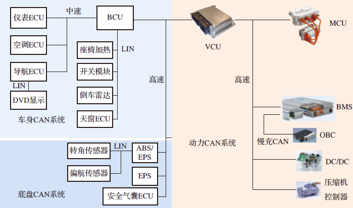
Figure 2 Fast Charging CAN Bus System
The New Energy CAN bus system transmits slow charging information, as shown in Figure 3. This system connects modules including VCU (Vehicle Control Unit), Compressor Controller, BMS, Charger ECU, Data Acquisition Terminal, Drive Motor Controller, High Voltage Box ECU, Electric Steering ECU, and Air Conditioning ECU. Additionally, it consists of the original vehicle’s CAN bus system made up of Body ECU, Combination Instrument ECU, etc.
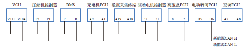
Figure 3 New Energy CAN Bus System
3
Volkswagen ID.4 CAN Network Topology
The ID.4 simplifies hundreds of control units into three domain controllers, namely ICAS1 (Vehicle Control Domain), ICAS2 (Intelligent Driving Domain), and ICAS3 (Intelligent Cockpit Domain). The ID.4 vehicle network is developed in parallel with the MEB platform, and ICAS stands for In-Car Application-Server.
The control unit code for ICAS1 is J533, which is the gateway control unit for fuel vehicles, indicating that ICAS1 has a gateway function. As shown in Figure 4, J533 connects to three bus systems: ① Power Bus System, connecting J623 Power Control Unit, J841 Motor Control Unit, and Remote Communication Control Unit; ② EV Bus System, connecting J979 Air Conditioning Control Unit, J840 Air Conditioning PTC Control Unit, DC/DC Converter A19, and J1050 On-Board Charger Control Unit; ③ Display and Operation Bus System, connecting R257 Engine Sound Simulation Control Unit.
(2) Network Transmission Rate
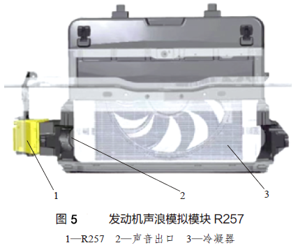
The transmission rate of the Power Bus System and EV Bus System is 2Mbit/s, while the transmission rate of the Display and Operation Bus System is 500kbit/s. This means that only simple actuators use the 500kbit/s rate, such as the engine sound simulation module R257 (Figure 5), while others use the 2Mbit/s rate.

(3) LIN Bus
J623 controls the radiator louver control unit V711 via LIN. J623 is installed below the right side of the dashboard (Figure 6), originally the code for the engine control unit of fuel vehicles, and is used for power control in the ID.4; J979 controls the Air Conditioning PTC control unit J848 and the Electric Compressor Control Unit J842 via LIN; J840 controls the Battery PTC Heater Z132 and the Distribution Box J1208~J1210 via LIN.
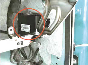
Figure 6 J623 Installation Position
The above images and text are excerpted fromMechanical Industry Press “Structure and Principles of Pure Electric Vehicles (Color Illustrated)”
“Structure and Principles of Pure Electric Vehicles (Color Illustrated)”
▼ Click on the book cover for more information
Senior Engineer Li Yuma summarizes years of maintenance experience, with new models, leading technology, easy to understand, quick to learn, and practical!
The back cover includes self-test questions + answers + PPT explanations, facilitating self-assessment for maintenance workers and students.
Related Articles
Image and text produced by: Li Chongkang
Editor: Xie Yuan
Reviewer: Li Jun

“Structure and Principles of Pure Electric Vehicles (Color Illustrated)” is available at the Tmall flagship store, JD.com, Dangdang, Youzan flagship store, and major Xinhua bookstores nationwide!!
Click on the bottom of the article“Read Original” to purchase the book at a discount!