Click on the above “ Technical Training ”, select “Pin to Top”
130,000+ industrial control professionals follow this WeChat platform: technical sharing, learning exchange, industrial control videos
1. Introduction
In recent years, computer control has been rapidly promoted and popularized. Industrial control computers, PLCs, frequency converters, touch screens, robots, and flexible manufacturing systems are widely applied in industrial production. Connecting different production devices into a network for data communication to achieve decentralized control and centralized management is a major trend in the development of computer control systems. Therefore, factory automation networks and PLC communication are important research topics in industrial control. Communication methods include parallel communication and serial communication. Parallel data communication transmits data in bytes, requiring multiple data lines and control lines for communication. Although parallel communication is fast, it has high costs due to the number of lines and is generally used for short-distance transmissions, such as communication between computers and printers. Serial data communication transmits data in binary bits, sending one bit at a time. It requires only one data line in one direction, which serves as both the data line and control line for communication. Serial communication uses fewer signal lines, needing only two lines (twisted pair), making it suitable for longer distances. Both computers and PLCs have standard serial communication interfaces, and serial communication is generally used in industrial control.
2. RS-485 Communication of Siemens S7-200 PLC
2.1. Serial Communication Interface Standards
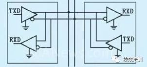
There are three interface standards for serial communication: RS-232C, RS-442A, and RS-485. RS-485 is a variant of RS-442A, which is full duplex with two pairs of balanced differential signal lines for sending and receiving. RS-485 has only one pair of balanced differential signal lines and cannot send and receive simultaneously.
Using the RS-485 communication interface and twisted pair can form a serial communication network, creating a distributed system with a maximum of 32 stations; new interface devices now allow connections to 128 stations.
2.2. Network Communication Protocol of S7-200
The network communication protocols of S7-200 include: Point-to-Point Interface Protocol (PPI), Multi-Point Interface Protocol (MPI), Profibus Protocol, TCP/IP Protocol, and User-Defined Protocol (Free Port Mode), totaling up to five types.
2.3. RS-485 Communication of Siemens S7-200 PLC
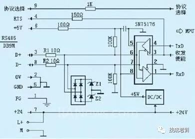
Serial communication is an economical and effective communication method in Siemens industrial network communications, with RS-485 being the most important component. In the diagram, R1 and R2 are ordinary resistors with a resistance of 10 ohms, which prevent overcurrent from damaging the chip when RS-485 signals D+ and D- are shorted. Z1 and Z2 are Zener diodes with a clamping voltage of 6V and a maximum current of 10A. The 24V power supply and 5V power supply share a ground without isolation. When common-mode interference voltage enters D+ or D-, the bridge rectifier circuit and Z1, Z2 can clamp the common-mode voltage to ±6.7V, thus protecting the RS-485 chip SN75176 (the allowable common-mode input voltage range for the RS-485 chip is -7V to +12V). This protection circuit can withstand common-mode interference voltage power of 60W, and neither the protection circuit nor the chip has anti-static measures.
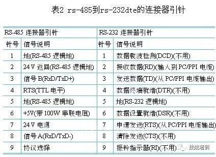
2.4. Conversion Between RS-232 and RS-485
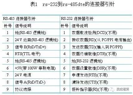
Since the serial port of a PC is RS-232 and the serial port of a PLC is RS-485, communication between the two requires the use of a PC/PPI cable. The corresponding relationship between the pinouts of RS-232 and RS-485 interfaces is shown in Tables 1 and 2.
3. Common Fault Analysis
3.1 Common Fault Phenomena
When the RS-485 port of the PLC is connected to a computer via a non-isolated PC/PPI cable, or when PLCs are connected to each other or to frequency converters, touch screens, etc., there is often damage to the communication port. The more common damage cases are as follows:
(1) R1 or R2 is burnt out, while Z1, Z2, and SN75176 are intact. This is due to large transient interference current passing through R1 or R2, the bridge rectifier, Z1 or Z2 to ground. Z1 and Z2 can withstand a maximum current impact of 10A, while the transient power generated on R1 or R2 is: 102×10=1000W, which will certainly burn them out.
(2) SN75176 is damaged, while R1, R2, and Z1, Z2 are intact. This is mainly due to static discharge or transient overvoltage occurring faster than the action speed of Z1, Z2. Static electricity is ubiquitous, and just the human body can generate ±15kV of static electricity.
(3) Z1 or Z2, SN75176 are damaged, while R1 and R2 are intact. This may be caused by high voltage low current transient interference voltage breaking down Z1 or Z2 and SN75176, as the current is small and the duration is short, R1 and R2 do not heat up and burn out.
3.2 Cause Analysis of Faults
From the analysis in 3.1, it is understood that the main cause of PLC interface damage is due to transient overvoltage and static electricity. The causes of transient overvoltage and static electricity are numerous and complex, such as the common grounding of the internal 24V and 5V power supplies of the PLC, where the output terminals L+ and M of the 24V power supply mixed with other devices may lead to ground potential changes, resulting in common-mode voltage exceeding the allowable range. Therefore, the EIA-485 standard requires connecting the signal grounds of each RS-485 interface with a low-resistance wire to ensure equal ground potential at each node and eliminate ground loop currents.
(1) When hot-plugging non-isolated connection cables, due to unequal potentials at both ends and the presence of many inductive and capacitive devices in the circuit, transient overvoltage or overcurrent is inevitably generated at the moment of plugging and unplugging. Based on this consideration, when performing communication connector plug-in and unplugging, it is best to keep the equipment powered off.
(2) Transient overvoltage or overcurrent generated by other devices connected to the RS-485 bus will also flow into the PLC. The more devices connected to the bus, the more factors that can cause transient overvoltage.
(3) When communication lines are long or have outdoor overhead lines, lightning must be considered as an interference factor. Lightning is a major natural source of interference, and the interference generated by lightning can be transmitted thousands of kilometers away. The time-domain waveforms of lightning interference superimpose into a large peak pulse on a random pulse background, and this enormous peak pulse energy will inevitably cause overvoltage on the lines, damaging PLCs and other connected devices in the communication network, which should be avoided or mitigated to reduce damage.
4. Solutions
4.1 Considering from the PLC Internal
(1) Use isolated DC/DC converters to isolate the 24V and 5V power supplies. We analyzed that Mitsubishi, Omron, Schneider PLCs, and Siemens’ Profibus interfaces are all like this.
(2) Choose high-grade RS-485 chips with comprehensive protection measures such as electrostatic protection, overheat protection, and input failure protection, such as SN65HVD1176D, MAX3468ESA, etc. These chips generally cost from tens to hundreds of yuan, while SN75176 costs only 1.5 yuan.
(3) Use new protective devices like TVS or BL surge absorbers with faster response speeds and higher transient power withstand capabilities, such as P6KE6.8CA with a clamping voltage of 6.8V and a transient power withstand of 500W. BL devices can withstand over 4000A of large current impacts. If using chips without fault protection, like SN75176, some processing can be done in software to avoid communication anomalies. That is, before entering normal data communication, the host should pre-drive the bus to greater than +200mV and maintain it for a period, allowing all nodes’ receivers to output a high-level signal. Thus, when sending effective data, all receivers can correctly receive the start bit and then the complete data.
(4) Use positive temperature coefficient self-resetting fuses (PTC), such as JK60-010, for R1 and R2. The normal resistance value is 5 ohms, which does not affect normal communication. When subjected to surge impacts, a large current flowing through PTC and protective devices (TVS or BL) will cause the resistance value of PTC to suddenly increase, rapidly reducing the surge current.
4.2 Considering from the PLC External
(1) Use isolated PC/PPI cables and avoid using cheap non-isolated cables (especially in industrial sites). The early PC/PPI cables produced by Siemens (6ES7901-3BF00-0XA0) were non-isolated, but they have now switched to isolated cables.
(2) When connecting the PLC’s RS-485 port to the network, use isolated bus connectors such as PFB-G, which automatically adapts to speeds of 0-1.5Mbps and has the same appearance and usage as Siemens’ non-isolated bus connections.
(3) Ensure that all third-party devices connected to the PLC, such as frequency converters, touch screens, etc., use RS-485 isolators (BH-485G) for isolation. This way, there is no electrical connection between RS-485 nodes, eliminating ground loop currents, and even if one node is damaged, it will not affect others.
(4) Good grounding is an important condition for the safe and reliable operation of industrial control systems, especially for industrial communication networks. In industrial communication networks, there should be at least three separate ground wires connected at one point. The first is the low-level circuit ground (i.e., signal ground), including digital ground, analog ground, signal ground, and DC ground; the second is the noise ground, which includes relay, motor, and high-power circuit grounds; the third is the chassis ground, specifically for mechanical shells, bodies, frames, and bases. This ground should be connected to the AC power supply ground. The AC power supply ground should be connected to the protective ground to avoid interference caused by uneven grounding points. RS-485 communication lines should use Profibus bus-specific shielded cables, ensuring that the shielding layer is connected to each device’s chassis and finally grounded.
(5) For systems with overhead lines, it is best to set up dedicated lightning protection facilities on the bus.
5. Conclusion
RS-485 communication is an important component of industrial network communication, and network and interface faults are common issues faced by engineering technicians, significantly affecting the stable operation of industrial control systems. Properly addressing these issues to ensure the stable and reliable operation of communication systems will greatly enhance factory automation efficiency. This brief discussion aims to provide certain assistance to engineering technicians in dealing with practical problems.Source: Siemens Official Website
Share with friends and take a look
ClickRead the Original to learn about electrical engineering, PLCs, frequency servo, CNC robots, and more