
1. Interference Resistance Design
The medical environment (such as hospitals, clinics, ambulances) is a typical complex electromagnetic environment, with numerous potential sources of interference:
-
Internal Interference: The device’s own switching power supply, motors (such as hospital beds, ventilators), and high-frequency noise from digital circuits.
-
External Interference: Other wireless devices (Wi-Fi, Bluetooth, walkie-talkies, mobile phones), large medical equipment (MRI, CT, X-ray machines, electrosurgical devices), and surges and pulses from the power supply network.
The design for interference resistance must be based on the three pillars of shielding, filtering, and grounding, and should be planned at a system level.
1. Spectrum Selection and Protocol Optimization
-
Prioritize the use of dedicated frequency bands: For example, WMTS, which is a frequency band specifically allocated for medical devices, has relatively less interference. For non-critical devices, the ISM band can be used, but coexistence mechanisms must be in place.
-
Adaptive Frequency Hopping Technology: For modules using frequency hopping protocols like Bluetooth, adaptive frequency hopping should be employed to actively avoid channels that are being interfered with.
-
Forward Error Correction: Adding redundant check codes to data packets allows the receiving end to automatically detect and correct errors within a certain range without needing retransmission, thus improving effective throughput in interference-prone environments.
-
Automatic Repeat Request: Combined with FEC, when the error exceeds the correction capability, the sender is requested to retransmit the data to ensure data integrity.
2. Hardware-Level Interference Resistance Design
-
PCB Layout and Routing
-
Partition Design: Strictly separate digital circuits, analog circuits, and RF circuits to avoid digital noise coupling into sensitive RF and analog sections.
-
RF Trace Control: Ensure 50-ohm impedance matching, keep traces short and straight, and avoid right angles and vias. Add grounding vias around RF paths for shielding.
-
Power Decoupling: Place decoupling capacitors of different values (e.g., 10uF, 0.1uF, 0.01uF) near the power pins of each chip to filter out power supply noise at different frequencies.
-
Ground Plane Integrity: Provide a complete and continuous ground plane to offer a low-impedance return path for high-frequency noise.
-
Shielding
-
Shielding Enclosure: Install a metal shielding enclosure for the entire wireless module or critical RF parts, ensuring it is well grounded to effectively isolate internal radiation from external interference.
-
Shielded Cables: Use shielded cables for internal connections to sensors or external antennas, ensuring the shielding layer is well grounded 360 degrees.
-
Filtering
-
Power Input Filtering: Use π-type filters, common mode chokes, etc., to suppress conducted interference from the power line.
-
Signal Line Filtering: Use ferrite beads or RC/LC filters on digital I/O, analog signal input ports, etc., to suppress high-frequency noise.
-
RF Front-End Filtering: Use SAW filters or ceramic filters after the power amplifier and before the low-noise amplifier to greatly suppress out-of-band interference and spurious emissions.
3. Fault Tolerance Design at the Software and Protocol Stack Level
-
Data Verification: In addition to the CRC check provided by the protocol, a stricter verification mechanism can be added at the application layer.
-
Heartbeat Packets and Connection Monitoring: Regularly send heartbeat packets to monitor link quality in real-time. If an unstable connection or disconnection is detected, immediately initiate reconnection or alarm mechanisms.
-
Data Caching and Resumption: Cache critical physiological data (such as ECG, blood oxygen) locally at the sender. When the network interruption is restored, the cached data can be automatically resumed to ensure data continuity.

2. Signal Optimization
Based on suppressing interference, how to further improve signal quality and transmission efficiency is the goal of signal optimization.
1. RF Front-End Optimization
-
Antenna Design and Selection
-
High-Efficiency Antennas: Choose or design antennas with high radiation efficiency and directional patterns that match the application scenario. For example, implantable devices may require omnidirectional antennas, while fixed monitoring devices may use directional antennas for longer distances.
-
Antenna Matching Network: Use a π-type matching network to ensure the antenna achieves conjugate impedance matching (usually 50 ohms) within the operating frequency band, maximizing energy transfer and enhancing transmission power and reception sensitivity.
-
Antenna Layout: Antennas should be placed away from metal objects and high-speed digital circuits, and positioned in specific areas of the device enclosure (such as under plastic windows) to reduce signal absorption and blockage.
-
Link Budget Optimization
-
Accurately calculate the link budget to ensure that the received signal strength is significantly higher than the receiver sensitivity at the expected communication distance and environment, leaving sufficient fade margin to cope with signal fluctuations.
-
Formula:
<span><span>Received Power = Transmit Power + Transmit Antenna Gain - Path Loss + Receive Antenna Gain</span></span> -
Optimize the link budget by appropriately increasing transmit power (within regulatory limits) and selecting high-gain antennas.
2. Data Link Layer Optimization
-
Adaptive Data Rate: Dynamically adjust the modulation scheme and data transmission rate of the wireless module based on real-time signal-to-noise ratio and bit error rate. Use higher-order modulation (such as 64-QAM) to increase the rate when the signal is good; automatically reduce the rate to more robust modulation schemes (such as QPSK, GFSK) when the signal is poor to ensure the connection remains stable.
-
Transmit Power Control: Automatically reduce transmit power while meeting communication needs. This not only reduces power consumption but also minimizes self-interference with other circuits within the device.
3. Data Preprocessing and Compression
-
Data Compression: Perform lossless or lossy compression on physiological signals (such as ECG, EEG) to reduce the amount of data that needs to be wirelessly transmitted, thereby shortening RF activation time, reducing the probability of interference, and lowering overall power consumption.
-
Intelligent Data Transmission: Not all data needs to be transmitted continuously in real-time. Thresholds can be set to trigger high-frequency transmission only when data anomalies or changes exceed specific ranges, while summary information is sent at lower frequencies during normal conditions.
3. Regulatory Compliance and Testing Verification
For medical devices, all designs and optimizations must comply with relevant regulations and standards.
-
EMC Standards: Must pass tests for electromagnetic compatibility standards for medical electrical equipment, such as YY 0505 or IEC 60601-1-2, including radiation emission, conducted emission, radiation immunity, conducted immunity, electrostatic discharge, and other items.
-
Radio Regulations: Must comply with the radio management regulations of the respective country/region, such as FCC Part 15/18 in the United States, and the RED directive in Europe, ensuring operation within permitted frequency bands and power ranges.
-
Reliability Testing: Long-term stability, stress, and extreme distance tests must be conducted in simulated complex electromagnetic environments (such as scenarios with Wi-Fi, microwave, and electrosurgical interference).

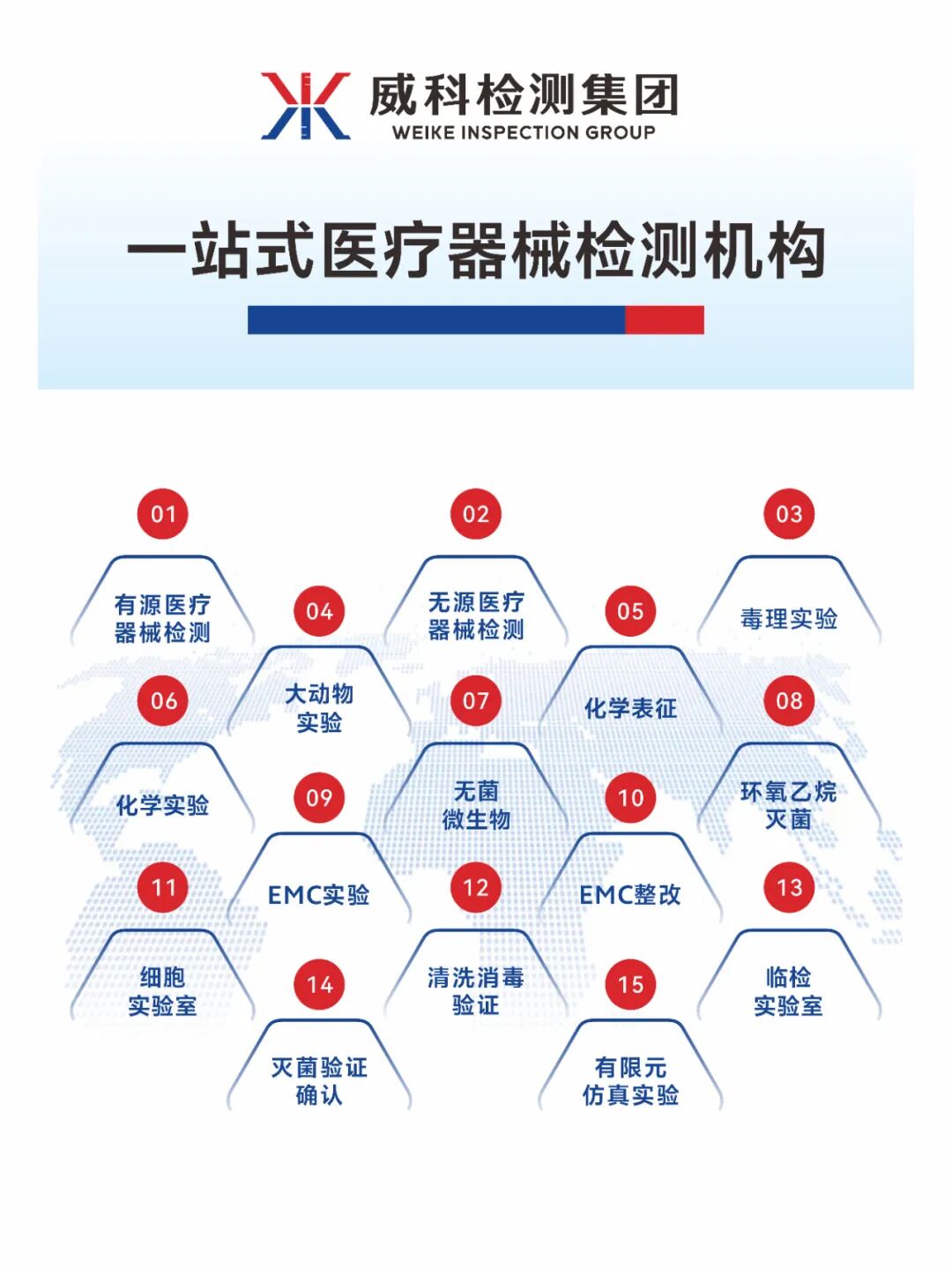
WIKA Testing Group has a professional inspection technology team and business operation team, equipped with advanced and precise testing equipment. The laboratory covers an area of approximately 12000 square meters, with environmental facilities including large animal experimental centers, SPF-level animal rooms, pathology testing rooms, chemical characterization analysis laboratories, microbiology laboratories, medical device performance testing, safety compliance EMC laboratories, etc.
WIKA Testing Group focuses on the medical device field, providing biological evaluation tests, large animal experimental research, chemical characterization testing, microbiological testing, disinfection and sterilization validation, physicochemical performance testing, cleanroom testing, packaging validation, aging tests, transportation experiments, system certification, safety compliance EMC testing and rectification, committed to co-creating an innovative platform for biomedical testing services and promoting high-quality development in the medical device industry.

 * The above materials are sourced from the internet. If your rights are infringed, please notify us, and we will handle it promptly.