*This article has been modified or fictionalized in certain “story” elements for various reasons. The “issues with a certain chip” mentioned in this article only describe the situation of my tested samples. At the end, there are two solutions and a summary.
Recently, I designed an IoT device using the ESP32 as the main control chip. To save space, I used the CH343 chip from Nanjing Qinheng as the USB to UART bridge chip, utilizing its RTS and DTR signals to achieve automatic download timing. The CH343P is a compact QFN16 package with a baud rate of up to 6M and complete serial flow control signal functionality, making it one of my favorite USB to UART bridge chips (except for its slightly higher price compared to the CH340 series).
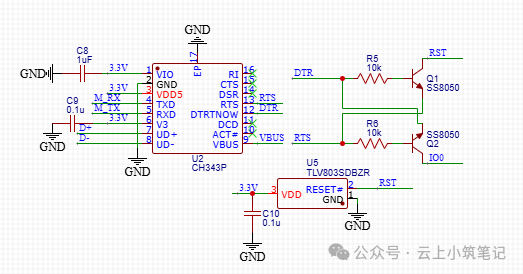
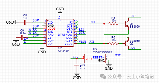
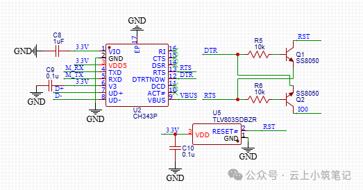
Based on integrated information from the internet, I drew the following schematic connection and, after careful inspection, believed it to be correct.
Considering that there is a large electrolytic capacitor on the main 3.3V power supply of the device, to avoid unexpected behavior of the ESP32 caused by too slow rise and fall times, I also designed a separate power monitoring reset IC—SGM803S, with a threshold voltage of 2.93V.
But just when I finished soldering the board and was ready to test… an unexpected problem arose.
Very bad timing caused my ESP32 to rotate
Upon first power-up, I habitually inserted a 600mA load switch into the USB input so that I could promptly detect any overcurrent caused by soldering mistakes. (Although this is unrelated to this article)
Connecting to the computer, the CH343 serial device was successfully recognized. I opened the Arduino IDE, modified the Ethernet PHY example, clicked the upload button, and then started to relax (x
After a while, the program finished uploading, but I did not see the Ethernet port light up.
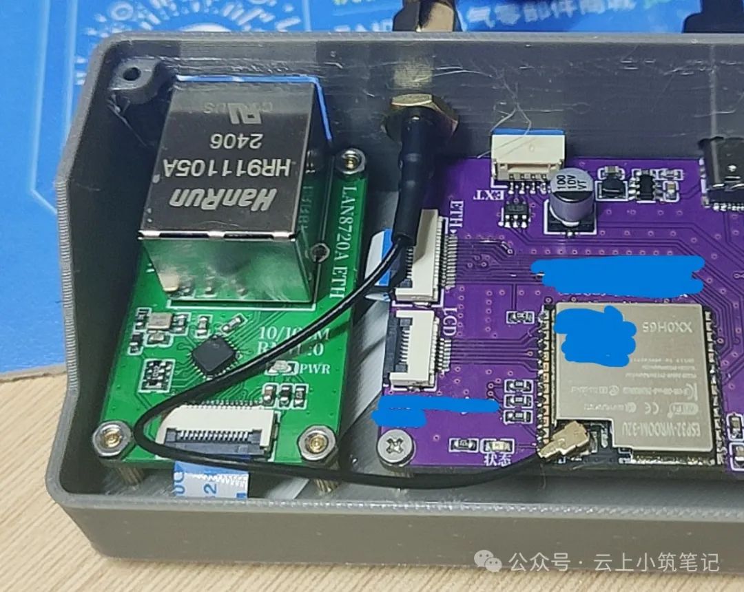
To add, I used the LAN8720A as the Ethernet PHY, connecting my custom module to the ESP32 main control board:
I first suspected that my PHY module was poorly soldered, or that the FPC connector was poorly soldered, so I opened the serial monitor to check the situation and pressed reset to run the program from the beginning. Unexpectedly, the startup log printed hit me hard:
ets Jul 29 2019 12:21:46
rst:0x1 (POWERON_RESET),boot:0x3 (DOWNLOAD_BOOT(UART0/UART1/SDIO_REI_REO_V2))waiting for download
Clearly, the ESP32 entered ISP download mode. I had considered during the design that using IO0 as a clock input might cause a certain probability of the ESP32 failing to start if the clock signal happened to be low at power-up. I directly removed the ribbon cable connecting the PHY module and tested again.
Surprisingly, the ESP32 still entered ISP download mode:
ets Jul 29 2019 12:21:46
rst:0x1 (POWERON_RESET),boot:0x3 (DOWNLOAD_BOOT(UART0/UART1/SDIO_REI_REO_V2))waiting for download
This left me puzzled: IO0 was clearly not connected to anything, so why was it still low? To prevent IO0 from floating and causing issues, I even connected a 10k pull-up resistor to IO0.
Who is pulling IO0 down (annoyed
Wait… is it really not connected to anything?
No, it isn’t. The connection on the IO0 pin includes a 10k pull-up resistor connected to the 3.3V main power supply, as well as a transistor connected to IO0, which supports the Arduino’s automatic entry into ISP download mode.
If DTR is low and RTS is high, then Q2 will conduct, pulling IO0 low.
But DTR should be high in the idle state, right?
This design is almost a 100% copy of a schematic I have used many times before, and theoretically, there should be no problem that can be consistently reproduced like this. But as for why it is “almost,” it is because this time I replaced the CH340C I originally used with the better CH343P.
Is the CH343P less stable than the CH340C? Not necessarily; there are countless boards on the market using the CH343 chip. Why is there such a consistently reproducible problem?
I suddenly realized that many ESP32 core boards using the CH343 chip on the market do not have the SGM803 voltage monitoring reset IC. Could it be that there is a compatibility issue between the CH343 and SGM803?
Thinking of this, I opened the oscilloscope to observe the waveforms of various signals at power-up, trying to find clues.
Big Oscilloscope is Watching You (unusual
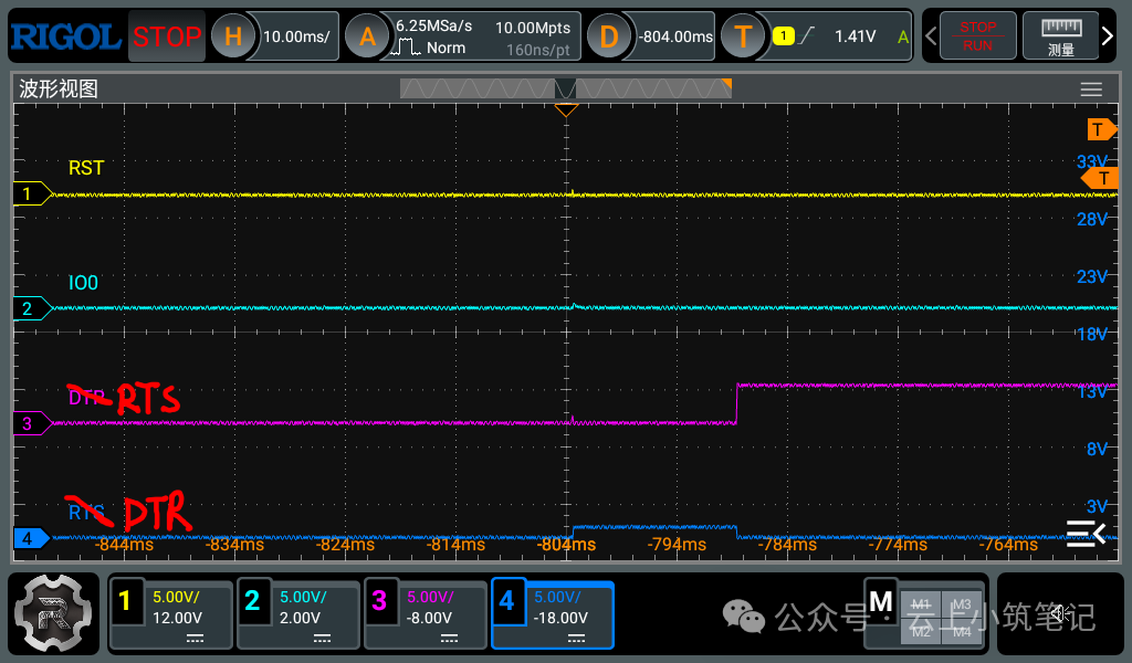
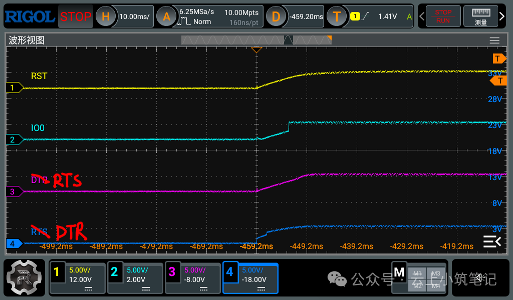
To avoid changes in flow control signals caused by CH343 communicating with the computer, I powered the ESP32 main control board with a mobile power supply and connected the oscilloscope probe to the RST, IO0, RTS, and DTR signals to capture the waveforms at power-up. (The labels marked during measurement were incorrect, I hand-corrected them)
I aligned the brief disturbance spike at power-up to the center of the screen’s horizontal axis and captured the following waveforms.
It is easy to notice that RST remained low for 50ms after power-up (controlled by SGM803, which has a fixed delay reset after power-up), and IO0 was also low; meanwhile, RTS jumped high at around 15ms, and DTR remained low.
Considering that I suspected the issue was related to the SGM803S, I removed the SGM803S and re-captured the power-up signal waveform.
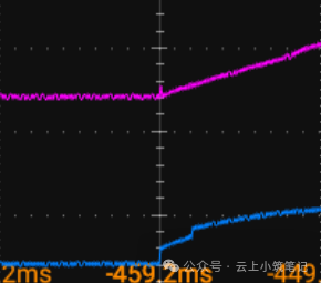
It can be seen that the RST signal has a normal RC reset circuit charging waveform, and IO0 shows a characteristic of a small slope rise when first powered up, reaching a strong pull-up to a stable high level after about 6ms; RTS and DTR signals both stabilize at a high level after 10ms. The state of the signals at this time is sufficient for the ESP32 to normally reset and start the program from Flash. Actual testing also proved that after removing the SGM803S, the startup anomaly no longer occurred. But I still want to find the cause of the problem.
Wait, although the waveforms of RTS and DTR both show a small slope rise, why does the DTR signal rise in two segments?
The figure shows that the DTR signal (blue) quickly rises to 1V at power-up, then after 2ms, there is another quick rise to over 2V+, and then it rises to a stable high level at a smaller slope.
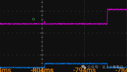
So what does the DTR signal waveform look like under abnormal conditions?
It is easy to see that the DTR signal (blue) also quickly rises to 1V at power-up, but after about 15ms, it rapidly drops back to a low level.
After carefully reviewing the CH343 manual CH343DS1, I noticed in its section 4 pin information:
This means that the waveform change of the DTR at power-up may be due to the CH343 detecting whether there is a pull-down resistor externally. If detected, the default DTR function of that pin switches to TNOW function. This function is commonly used for direction control of 485 transceivers, with the idle state defaulting to low, which also leads to the situation where DTR is continuously pulled low when problems occur.
But where is the pull-down resistor on the DTR pin? Returning to this diagram, it is not clear where there is a pull-down on the DTR pin:
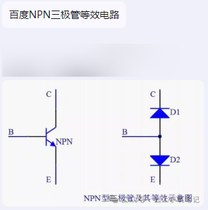
Q2 conducting in reverse to allow current to flow from the emitter to the collector seems a bit absurd. Could it be that Q1’s base current is too large? Indeed, during normal startup, the RTS voltage rises almost synchronously with the DTR voltage, and Q1 is basically in the cutoff region due to the small Vbe.
Noticing that the problem only occurs under the condition that RST is strongly pulled low at power-up (provided by SGM803S) for a certain time, I narrowed the problem down to the interaction between DTR and RST.
But I looked for a long time and still couldn’t figure out how the current from Q1’s base flows to the collector.
There is still a gap between ideal and reality
At this point, a friend in the group pointed out the key to the problem:
Yes, the transistor has Ibc current! It is just that in normal circumstances, it is much smaller than Ice and Ibe, so it is ignored in large signal analysis, but it does exist. Since the collector has the strong pull-down of the reset IC, the weak pull-up current of DTR at power-up (approximately 15-90uA when VIO=3.3V) flows from the base of Q1 to the collector and then into GND, causing the CH343 to think it has “detected an external DTR pull-down resistor.”
At the same time, this friend also kindly provided Solution 1: add a stronger pull-up resistor of around 1K on the DTR pin to VIO, so that due to the limited Ibc current, it would not be enough to pull the DTR voltage low enough, preventing it from being judged by CH343 as “external pull-down.”
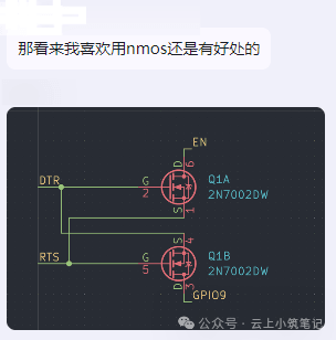
Another friend also provided Solution 2: replace the NPN transistor with an NMOS (connection method see diagram). The NMOS’s Igss is in the hundred nA range, which is completely insufficient to affect the CH343’s DTR pull-down detection. However, such designs using NMOS to generate automatic download timing are not common in commercial products. Perhaps it’s because MOSFETs are a bit more expensive? Or maybe it’s just a direct copy of the official DevkitC automatic download transistor circuit? Or perhaps I am just lacking knowledge.
After testing, both solutions provided by my friends successfully resolved the issue I encountered, and I would like to express my gratitude to them.
To summarize, the problem I encountered arose from the coincidence of the following three normally problem-free factors:
-
Compared to the CH340 series, the DTR pin of the CH343 supports switching to a second function with an external pull-down resistor, and the default state of that second function is low;
-
The transistor automatic download circuit draws a certain amount of current from DTR and RTS;
-
The SGM803S and other reset ICs have a fixed delay of about 100ms at power-up, during which the RST pin is strongly pulled down to ground (even if such reset ICs are not used, as long as the RST pin has a strong pull-down for more than 15ms at power-up, this problem can occur, including powering up while holding the reset button);
During the analysis of the problem, I habitually applied the “simplified conclusion” of transistor analysis when analyzing the transistor circuit, neglecting the actual situation, which caused me to overlook the fact that Ibe led to excessive base current pulling down the DTR voltage. This is also something I need to be cautious about in the future.
