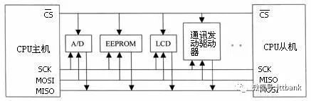
1. SPI BusThe Serial Peripheral Interface (SPI) bus technology was introduced by Motorola and is a synchronous serial interface. Most MCUs (Microcontrollers) produced by Motorola, such as the 68 series MCUs, are equipped with SPI hardware interfaces. SPI is used for full-duplex, synchronous serial communication between the CPU and various peripheral devices. SPI can simultaneously transmit and receive serial data. It requires only four wires to complete communication between the MCU and various peripheral devices. These four wires are: Serial Clock Line (CSK), Master In/Slave Out Data Line (MISO), Master Out/Slave In Data Line (MOSI), and Low Active Slave Select Line (CS). These peripheral devices can be simple TTL shift registers, complex LCD display drivers, A/D, D/A converter subsystems, or other MCUs. When SPI is operating, the data in the shift register is output bit by bit from the output pin (MOSI) (most significant bit first), while the data received from the input pin (MISO) is shifted into the shift register (most significant bit first). After sending a byte, the byte data received from another peripheral device enters the shift register. The main SPI clock signal (SCK) synchronizes the transmission. Its typical system block diagram is shown below.
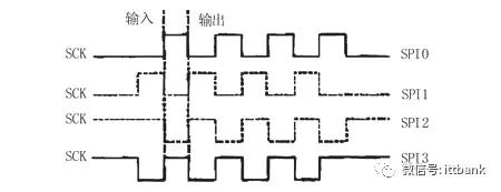
SPI has the following main features: it can simultaneously transmit and receive serial data; • It can function as either a master or a slave; • It provides a programmable clock frequency; • It sends an end-of-transmission interrupt flag; • It has write conflict protection; • It has bus contention protection, etc. Figure 2 shows four modes of operation for the SPI bus, with SPI0 and SPI3 modes (solid lines) being the most widely used:
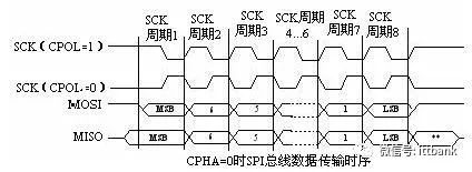
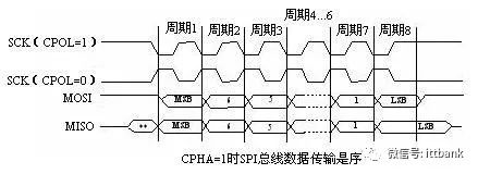
The SPI module can configure its output serial synchronous clock polarity and phase according to the requirements of the peripheral devices for data exchange. The clock polarity (CPOL) does not significantly affect the transmission protocol. If CPOL=0, the idle state of the serial synchronous clock is low; If CPOL=1, the idle state of the serial synchronous clock is high. The clock phase (CPHA) can be configured to select one of two different transmission protocols for data transmission. If CPHA=0, data is sampled on the first edge (rising or falling) of the serial synchronous clock; If CPHA=1, data is sampled on the second edge (rising or falling) of the serial synchronous clock. The SPI master module and the peripheral communicating with it should have consistent clock phase and polarity. The timing of the SPI bus interface is shown in the diagram.
2. CAN Bus What is CAN Bus? CAN, short for Controller Area Network, was first proposed by Bosch in Germany and is one of the most widely used field buses internationally. CAN is a multi-master serial communication bus designed with high bit rates, high electromagnetic interference resistance, and the ability to detect any errors on the bus. Even at a signal transmission distance of 10 km, CAN can still provide a data transmission rate of up to 50 Kbit/s.
CAN has several superior characteristics: A. Low cost with extremely high bus utilization; B. Data transmission distances can reach up to 10 km, with transmission rates up to 1 Mbit/s; C. Reliable error handling and detection mechanisms, allowing for automatic retransmission of corrupted messages; D. Nodes can automatically exit the bus in case of serious errors; E. Messages do not contain source or destination addresses, only identifiers to indicate functional and priority information; Due to human, natural, and other external influences, and the pursuit of safety, reliability, authenticity, and real-time performance in bus systems, our requirements for communication methods and devices have become higher, making networks based on CAN bus our best choice. CAN Bus Field buses are one of the hot topics in today’s automation technology development, hailed as the computer local area network of the automation field. Its emergence provides strong technical support for real-time and reliable data communication between nodes in distributed control systems. CAN (Controller Area Network) belongs to the category of field buses and is an effective serial communication network that supports distributed control or real-time control. Compared to many RS-485-based distributed control systems, the distributed control system based on the CAN bus has significant advantages in the following aspects: First, the CAN controller operates in a multi-master mode, where each node in the network can compete to send data to the bus using a lossless structure with bit-by-bit arbitration based on bus access priority (determined by the message identifier), and the CAN protocol eliminates station address coding, replacing it with coding of communication data, allowing different nodes to receive the same data simultaneously. These characteristics enable strong real-time data communication between nodes in a CAN bus network and facilitate redundancy structures, enhancing system reliability and flexibility. In contrast, RS-485 can only form master-slave structured systems, and communication can only be conducted through master polling, resulting in poorer system real-time performance and reliability; Secondly, the CAN bus connects to the physical bus through the CAN controller interface chip 82C250, where the CANH terminal can only be in a high or floating state, and the CANL terminal can only be in a low or floating state. This prevents situations like those in RS-485 networks, where errors can lead to multiple nodes sending data to the bus simultaneously, causing a short circuit and damaging certain nodes. Moreover, CAN nodes can automatically disable outputs under serious error conditions to prevent the operations of other nodes on the bus from being affected, thus avoiding