 Introduction: This article discusses the potential interference from high-frequency electromagnetic waves in electronic signal processing circuits in practice. These situations are often omitted in ordinary classrooms and textbooks. The additional peripheral resistors and capacitors that seem unrelated to ordinary signal processing play a crucial role in ensuring circuit stability. Therefore, while encountering problems may cause trouble, observing, analyzing, and solving them will further expand one’s knowledge and enhance problem-solving abilities.01 Problem Statement1.1 Source of the ProblemStudents raised issues encountered during the construction of smart cars related to signal acquisition (pulses in electromagnetic signals, black screen of camera signals), which sparked interest among many students, and they shared their views in the “comments”.Comment 1:Our car also experiences jumps; we never thought it was due to static electricity. Is it really due to static?Comment 2:After I turn on Bluetooth, one of the inductors shows spikes; touching the Bluetooth causes the op-amp spikes to disappear.
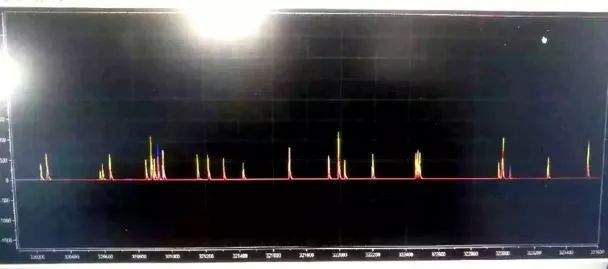 ▲ Figure 1.1 Signal with Spike Interference1.2 Preliminary Problem AnalysisRegarding the spike pulse interference in electromagnetic signal acquisition, some students suggested that this might be due to interference from the Bluetooth module. To facilitate the setting of car model operating parameters and monitor its operating status, students added Bluetooth and WiFi modules for data transmission in the car model. These wireless communication modules use approximately 2.4GHz ISM band radio waves for data transmission. Many signal transmission leads on the car model can easily introduce high-frequency radio waves into the circuit board’s lines. How do these high-frequency signals cause signal interference, and how can it be prevented?02 Principle IntroductionOperational amplifiers (OPAs) are widely used in circuit design for signal conditioning: amplification, filtering, level shifting, etc. The gain of a typical operational amplifier decreases as the signal frequency increases, typically characterized by the Gain Bandwidth Product (GBP). When the signal frequency reaches the GBP, the gain of the op-amp drops to 1.Common op-amps have a GBP around 1MHz, for example: LMV321<1MHz, LF351:4MHz. LM385<0.7MHz. For wireless communication module electromagnetic wave signals operating at 2.4GHz, since these signals far exceed the GBP, theoretically, even if these signals enter the circuit, the op-amp will attenuate them to very low voltage levels.However, the actual situation is not so. In fact, the electrostatic discharge (ESD) diodes, input structures, and other nonlinear components contained within the amplifier will “rectify” RF signals at the amplifier’s input. Therefore, the actual effect is that RF signals are converted into a DC offset voltage, which adds to the amplifier’s input offset voltage, thus affecting the output voltage of the operational amplifier.The parameter reflecting the impact of high-frequency signals on the op-amp is EMIRR (Electromagnetic Interference Rejection Ratio). This can be calculated by measuring the amplitude of the high-frequency input signal against the DC offset of the op-amp output.
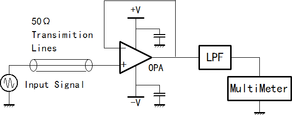 ▲ Figure 2.1 Measuring the EMIRR Circuit of OPAMPA well-designed operational amplifier can have excellent EMIRR capabilities. The following graph shows the EMIRR curve of TI’s OPA333; it can be seen that at a signal frequency of 1000MHz, this op-amp has an EMIRR of 120dB, which is a very high suppression level.
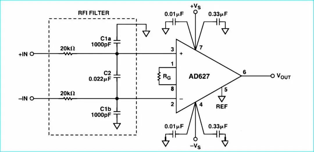
 ▲ Figure 2.2 EMIRR Curve of TI’s OPA333Ordinary operational amplifiers do not exhibit such good EMIRR performance.03 Problem AnalysisIf Bluetooth and WiFi modules are installed on a small car model for data transmission, the electromagnetic waves they emit can be introduced into the control circuit through various leads on the car model. If there is no good filtering protection for the input signals, combined with low EMIRR of the used op-amps, it can cause changes in the DC component of the output signal from the op-amp. Since Bluetooth and WiFi modules use data packets and send data intermittently, many spike interference signals will appear in the signals on the line.Understanding that wireless RF signals can cause interference in the op-amp output, the solution is to add high-frequency filtering circuits at the input ports with long external leads. This allows these externally introduced high-frequency signals to be significantly attenuated before reaching the op-amp pins. Additionally, high-frequency filter capacitors are also added near the power and ground pins of the op-amp to prevent RF signals from interfering with the chip from the power port. The following circuit is a reference design circuit section provided in the AD627 data sheet.
 ▲ Figure 3.1 Adding RF Signal Filtering Circuit at OPAMP Input Lines04 Experimental Verification4.1 Experiment 1: Impact of Bluetooth on OPAMPObserve the impact of the Bluetooth transmission module on the op-amp.Using LMV358 to build a non-inverting amplifier with a gain of 50. A lead is added at the input to simulate an external signal lead. A Bluetooth module is placed 5 cm next to the circuit board, with its antenna parallel to the lead.
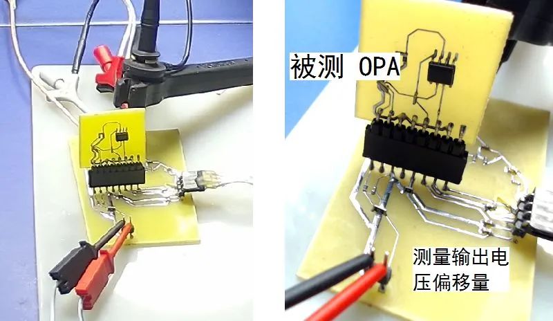
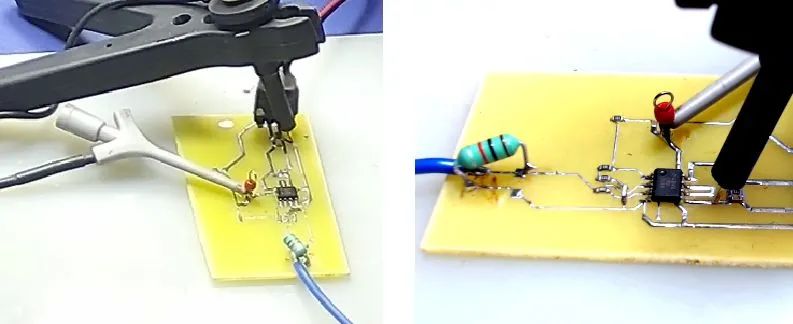 ▲ Figure 4.1.1 Testing the Impact of the Bluetooth Module on OPAMPIn the above circuit, no high-frequency filtering circuit has been added at the input port. High-frequency signals on the lead can directly reach the input port of LMV358.When the Bluetooth module is not working, the op-amp output is a stable level. When the Bluetooth module sends data, spike interference pulse signals appear in the op-amp output.
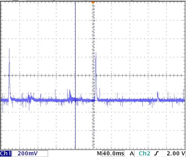 ▲ Figure 4.1.2 Spike Interference Signal in LMV358 OPAMP OutputIf a filtering circuit composed of inductors and capacitors is added to the test circuit board, under the same external conditions, the op-amp output will no longer have spike interference signals.4.2 Experiment 2: Testing OPAMP EMIRRFor three types of op-amps: OP07, LMV321, LM351, build a non-inverting amplifier circuit as shown in the previous figure 2. Using a standard signal source, input a 0.7~10MHz high-frequency signal with a peak-to-peak value of 1V into the circuit. Measure the changes in the DC component of the output voltage.▲ Figure 4.2.1 Testing EMIRR CircuitSince the GBP of these three OPs is greater than 0.7MHz, it can be seen that below 0.7MHz, the DC component of the output voltage basically does not change with the frequency of the signal. When the input signal frequency exceeds 1MHz, the DC value starts to fluctuate significantly. Among them, the DC operating point of LM358 decreases, while OP07 and LMV321 increase. The range of change is smallest for LMV321 and largest for LM358. Since the output signal frequency of the signal source is limited, the test cannot directly reach the 2.4GHz band.
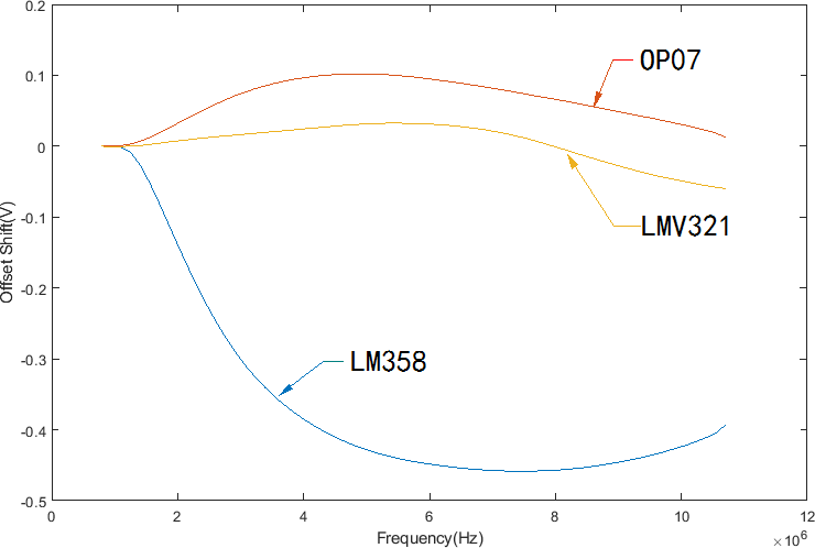 ▲ Figure 4.2.2 Change in DC Offset of Three OPAMPs Under High-Frequency Input SignalsThe above results show that different operational amplifiers have significantly different suppression capabilities for RF interference. In environments with significant RF signals, it is necessary to consider adding high-frequency filtering circuits in circuit design to prevent circuit interference.05 Discussion and ConclusionThis article discusses the potential interference from high-frequency electromagnetic waves in electronic signal processing circuits in practice. These situations are often omitted in ordinary classrooms and textbooks. The peripheral resistors and capacitors added in the circuit in Figure 4, which seem unrelated to ordinary signal processing, play a crucial role in ensuring circuit stability. Therefore, while encountering problems may cause trouble, observing, analyzing, and solving them will further expand one’s knowledge and improve problem-solving abilities.5.1 Placing RF Interference in Circuit DesignIn future circuit designs, due to the potential presence of numerous RF communication modules (Bluetooth, WiFi, mobile phones, etc.), in addition to ensuring that the basic functions of the circuit meet signal processing requirements, it is also necessary to consider the electromagnetic compatibility (EMC) of the circuit, ensuring that the device can operate stably under any conditions. Otherwise, inexplicable situations may arise.As it is electromagnetic wave interference, the phenomenon of interference will be affected by many specific situations. Just like the comments from students at the beginning, simply touching the Bluetooth module can eliminate the interference. Therefore, when faced with problems, do not jump to conclusions easily. Carefully distinguish whether the interference is caused by static electricity or RF signals, as this will greatly help in solving the final problem.
 ▲ Figure 5.1 APPLE Learning MethodAuthor: Zhuo QingHAPPY NEW YEAR