
Many electricians habitually use a shake table to measure the condition of motors in their daily work, which is undoubtedly a common and relatively safe testing method. Today, I will share how to use a multimeter to test the condition of motors, so that in case a shake table is unavailable, you can still measure relevant conditions without delaying your work progress!
Measurement Method for Three-Phase Motors:
Set the digital multimeter to the 200Ω range and measure the three-phase power lines on the motor two at a time. If the resistance values from the three measurements are equal or very close, it indicates that the three-phase windings are well connected.

Next, open the motor’s junction box and remove the connecting copper pieces from the terminals, which disconnects the U, V, and W windings. Set the multimeter to the highest resistance range and measure any two terminals of the U, V, and W windings. If the resistance shows infinity, it indicates that the motor’s inter-phase insulation is normal.
Finally, use the maximum resistance range of the multimeter to measure the resistance between any terminal of U, V, W and the casing. If the resistance values are all infinite, it indicates that the motor insulation is fine and it can be powered on for a startup test.
Measurement Method for Single-Phase Motors:
When measuring a single-phase motor, set the digital multimeter to the 2K range and first measure the resistance of the main winding, which is generally in the tens to hundreds of ohms, varying with the motor power.
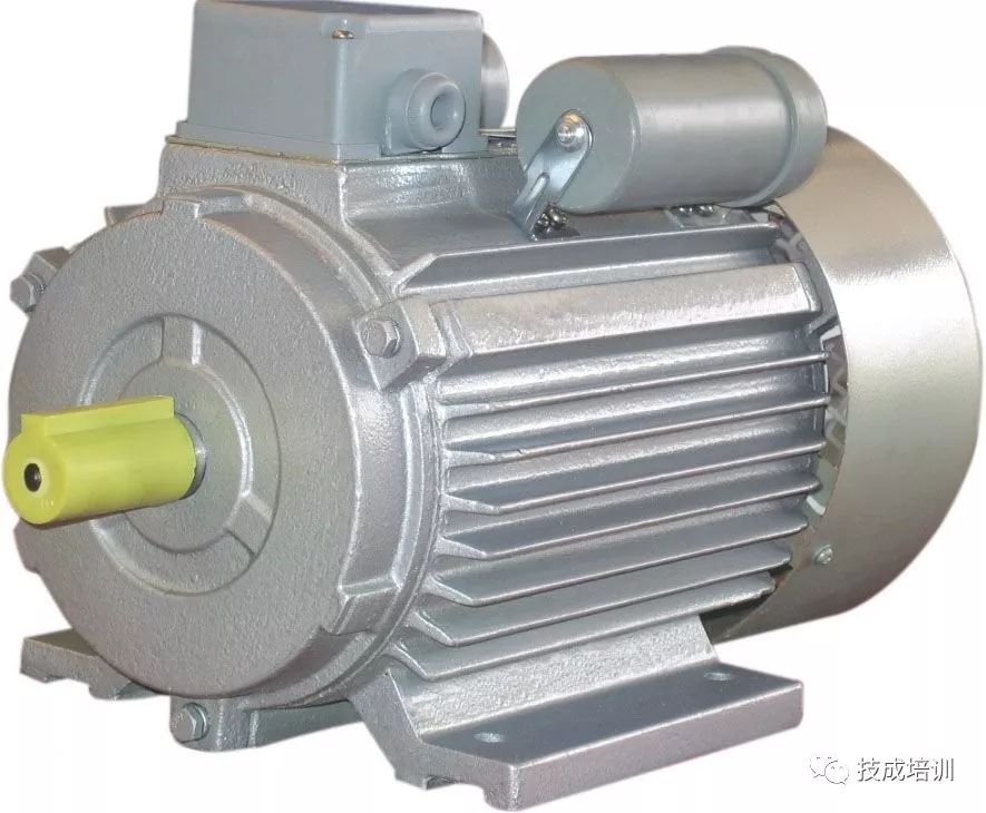
The resistance of the auxiliary winding is slightly larger or the same as that of the main winding. If the resistances of the main and auxiliary windings are normal, then check the insulation between the main and auxiliary windings. Set the multimeter to the highest resistance range, and while the main and auxiliary windings are disconnected, connect one probe to any terminal of the main winding and the other probe to any terminal of the grounded auxiliary winding. An insulation resistance showing infinity is normal. Finally, measure the insulation resistance between the two windings and the casing. Connect one probe to the winding and the other probe to a conductive part of the motor casing; showing infinity is normal.
Source: Jicheng Training
Business Cooperation: 010—88379790 ext. 802
Disclaimer: This article is a network reprint, and the copyright belongs to the original author. However, due to the numerous reprints, it is impossible to confirm the true original author, so only the source of the reprint is indicated. If any videos, images, or texts used in this article involve copyright issues, please notify us immediately, and we will confirm the copyright based on the materials you provide and pay remuneration according to national standards or delete the content immediately! The content of this article reflects the original author’s views and does not represent the endorsement of this public account regarding its views or authenticity.
 Scan the code to add the editor as a friend
Reply 4: Join the Industrial Robot Technology Exchange Group 4 (focusing on industrial robot applications, automation production lines, etc.)
Reply 5: Join the Industrial Robot Technology Exchange Group 5 (focusing on industrial robot components, including body, drive system, control system, etc.)
Reply 6: Join Group 6 (focusing on PLC technology, programming technology, etc.)