
Introduction: In this issue, we will provide a detailed introduction to the usage methods and precautions of commonly used instruments, to help everyone grasp the relevant knowledge more quickly.1. Usage of Multimeter
The multimeter can measure direct current, direct voltage, alternating voltage, and resistance, and some can also measure power, inductance, and capacitance, making it one of the most commonly used instruments by electricians.
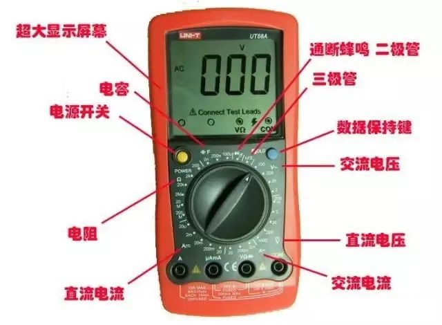
1. Basic Structure and Appearance of Multimeter
The multimeter consists of three parts: the indicating part, the measuring circuit, and the switching device. The indicating part is usually a moving coil microammeter, commonly known as the meter head; the measuring part converts the measured electrical quantity into a small direct current suitable for the meter head, usually including shunt circuits, voltage divider circuits, and rectifier circuits; the measurement and range selection of different types of electrical quantities are achieved through the switching device.
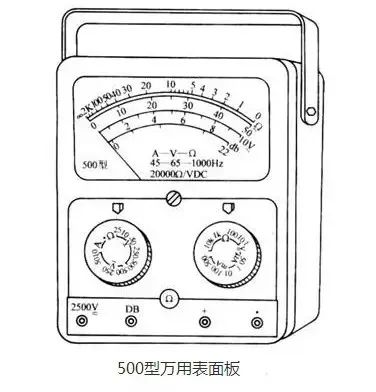
2. Usage Methods of Multimeter
(1) Correctly select the terminal (or socket)
The red probe must be connected to the red terminal (or the socket marked with a “+” sign), and the black probe should be connected to the black terminal (or the socket marked with a “—” sign). Some multimeters have measuring terminals for AC and DC up to 2500 volts; when using, the black probe should still connect to the black terminal (or the “—” socket), while the red probe connects to the 2500-volt terminal (or socket).
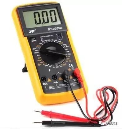
(2) Correctly select the position of the switch
Select the switch position according to the measurement object. For example, when measuring current, turn the switch to the corresponding current range, and when measuring voltage, turn it to the corresponding voltage range. Some multimeters have two switches on the panel, one for selecting the measurement type and the other for selecting the measurement range. You should first select the measurement type and then the measurement range.
(3) Choose an appropriate range
Based on the approximate range of the measurement, turn the switch to the appropriate range for that type. When measuring voltage or current, it is best to keep the pointer within half to two-thirds of the range for more accurate readings.
(4) Correctly read the values
On the scale of the multimeter, there are many scales that are suitable for different measured objects. Therefore, when measuring, while reading the values on the corresponding scale, also pay attention to the matching of the scale reading and the range to avoid errors.
(5) Correct use of the ohm range
1) Select the appropriate multiplier range
When measuring resistance, the multiplier range should be selected to make the pointer stop at a less dense part of the scale; the closer the pointer is to the middle of the scale, the more accurate the reading, while moving left makes the scale denser and the accuracy worse.
2) Zero adjustment
Before measuring resistance, the two probes should touch each other, and at the same time, turn the “zero adjustment knob” to make the pointer point exactly to the zero position on the ohm scale. This step is called zero adjustment in the ohm range. Each time you switch the ohm range, this step must be repeated to ensure measurement accuracy. If the pointer cannot be adjusted to zero, it indicates that the battery voltage is insufficient and needs to be replaced.
3) Do not measure resistance while powered
When measuring resistance, the multimeter is powered by a dry battery; the resistance being measured must not be powered to avoid damaging the meter head. During the use of the ohm range, do not short-circuit the two probes to avoid wasting battery.
(6) Pay attention to operational safety
1) When using the multimeter, be careful not to touch the metal part of the probes to ensure safety and measurement accuracy.
2) When measuring high voltage or large current, do not turn the switch while powered, as this may burn out the switch.
3) After using the multimeter, it is best to turn the switch to the highest AC voltage range, which is the safest setting for the multimeter to prevent damage due to negligence during the next measurement.
4) Before the probes touch the measured circuit, conduct a thorough inspection to ensure that all parts are in the correct position.
2. Usage of Megohmmeter
The megohmmeter, commonly known as the shake meter, is used to measure high resistance and insulation resistance, with the unit of measurement being megohms (MΩ), hence the name megohmmeter. There are many types of megohmmeters, but their functions are generally similar.
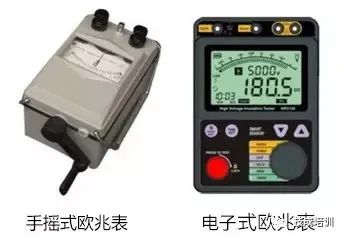
1. Selection of Megohmmeter
The voltage level of the megohmmeter should be higher than the insulation voltage level of the measured object. Therefore, when measuring the insulation resistance of devices or circuits with a rated voltage below 500V, a 500V or 1000V megohmmeter can be selected;
When measuring the insulation resistance of devices or circuits with a rated voltage above 500V, a 1000-2500V megohmmeter should be used; when measuring insulators, a 2500-5000V megohmmeter should be selected.
In general, when measuring the insulation resistance of low-voltage electrical equipment, a megohmmeter with a range of 0-200MΩ can be used.
2. Method of Measuring Insulation Resistance
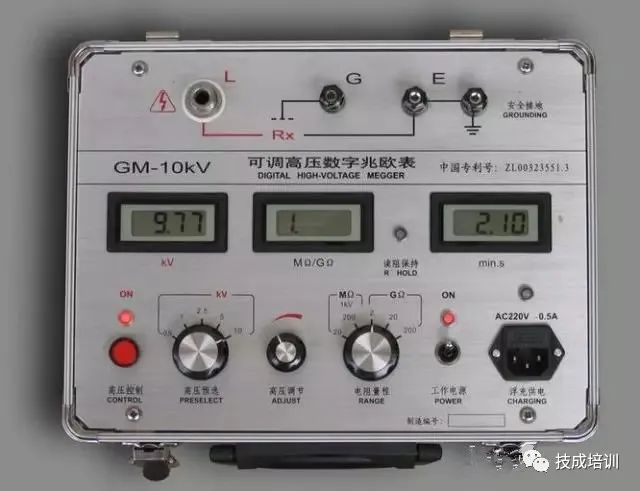
The megohmmeter has three terminals; the two larger upper terminals are marked “Ground” (E) and “Line” (L), while the smaller lower terminal is marked “Protective Ring” (or “Shield”) (G).
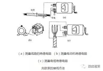
(1) Insulation resistance of the line to ground
Connect the “Ground” terminal (E terminal) of the megohmmeter reliably to ground (usually to a grounding body), and connect the “Line” terminal (L terminal) to the measured line, as shown in the figure below.
After connecting, turn the megohmmeter clockwise, gradually increasing the speed, and maintain a steady speed of about 120 revolutions per minute. When the speed stabilizes, the pointer of the meter will also stabilize, and the value indicated by the pointer is the insulation resistance of the measured object.
In practical use, the E and L terminals can also be connected interchangeably, that is, E can connect to the measured object, and L can connect to the ground (i.e., grounding), but the G terminal must not be connected incorrectly.
(2) Measuring the insulation resistance of motors
Connect the E terminal of the megohmmeter to the casing (i.e., ground), and connect the L terminal to the winding of a certain phase of the motor, as shown in the figure above. The insulation resistance value measured is the insulation resistance of that phase to ground.
(3) Measuring the insulation resistance of cables
When measuring the insulation resistance between the conductive core of the cable and the cable sheath, connect the E terminal to the cable sheath, connect the L terminal to the core, and simultaneously connect the G terminal to the insulation layer between the cable sheath and core, as shown in the figure above.
3. Usage Notes
(1) Before use, conduct open and short circuit tests. Keep the L and E terminals in a disconnected state, shake the megohmmeter, and the pointer should point to “∞”; short-circuit the L and E terminals, and slowly turn; the pointer should point to “0”. If both requirements are met, it indicates that the megohmmeter is functioning properly.
(2) When measuring the insulation resistance of electrical equipment, the power supply must be turned off first, and the equipment should be discharged to ensure personal safety and measurement accuracy.
(3) The megohmmeter should be placed in a horizontal position during measurement, and it should be held firmly to prevent shaking while shaking; the shaking speed should be 120 revolutions per minute.
(4) The connecting wires should be made of multi-strand soft wire and must have good insulation. The two connecting wires should not be twisted together to avoid inaccurate measurement data.
(5) After measurement, the measured object should be discharged immediately. Do not touch the measuring part of the measured object or remove the wires with your hands before the shaking handle of the meter has stopped turning and the measured object has been discharged to prevent electric shock.
3. Ammeter
An ammeter is connected in series with the circuit being measured to measure its current value. Depending on the nature of the current being measured, it can be classified into DC ammeters, AC ammeters, and dual-purpose ammeters. In terms of measurement range, there are microammeters, milliampere meters, and ampere meters. According to the action principle, they can be divided into moving coil, electromagnetic, and electrodynamic types.
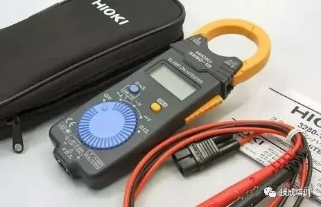
▲ Portable Clamp Meter
1. Selection of Ammeter
When measuring DC current, it is common to use a moving coil meter, but electromagnetic or electrodynamic meters can also be used. When measuring AC current, electromagnetic meters are more commonly used, but electrodynamic meters can also be used. For situations requiring high measurement accuracy and sensitivity, a moving coil meter should be used; for situations where measurement precision is not strict and the measured current is large, a low-cost electromagnetic meter with a strong overload capacity is often chosen.
The range of the ammeter should be determined based on the size of the current being measured, ensuring that the measured current value is within the range of the ammeter. When the size of the measured current is unclear, a larger range ammeter should be used first to avoid damage due to overload.
2. Usage Methods and Precautions
(1) The ammeter must be connected in series with the measured circuit.
(2) When measuring DC current, the polarity of the ammeter connection terminals “+” and “—” must not be reversed, or the instrument may be damaged. Moving coil ammeters are generally only used for measuring DC current.
(3) Select an appropriate range based on the size of the measured current. For ammeters with two ranges, they have three connection terminals; when using, be sure to check the range markings on the connection terminals and connect the common terminal and one range terminal in series with the measured circuit.
(4) Choose an appropriate accuracy to meet the measurement needs. Ammeters have internal resistance; the lower the internal resistance, the closer the measurement result will be to the actual value. To improve measurement accuracy, an ammeter with lower internal resistance should be used as much as possible.
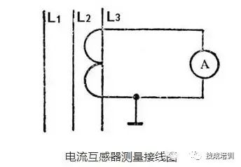
(5) When measuring large AC currents, current transformers are often used to extend the range of the AC ammeter. The rated current of the secondary coil of the current transformer is generally designed to be 5 amperes, and the AC ammeter used with it should also have a range of 5 amperes. The reading of the ammeter multiplied by the transformation ratio of the current transformer gives the actual current value being measured. When using a current transformer, ensure that the secondary coil and core are reliably grounded, and do not install a fuse at one end of the secondary coil; it is strictly prohibited to operate with an open circuit.
4. Voltmeter
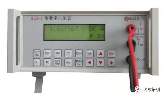
A voltmeter is connected in parallel with the circuit being measured to measure the voltage value of the measured circuit. Depending on the nature of the voltage being measured, it can be classified into DC voltmeters, AC voltmeters, and dual-purpose voltmeters. In terms of measurement range, there are millivolt meters and volt meters. According to the action principle, they can be divided into moving coil, electromagnetic, and electrodynamic types.
1. Selection of Voltmeter
The selection principles and methods for voltmeters are basically the same as those for ammeters, mainly considering aspects such as the measurement object, measurement range, required accuracy, and instrument price. For measurements that do not require high precision, electromagnetic voltmeters are generally used. For measurements that require high precision and sensitivity, multi-range moving coil voltmeters are commonly used, among which the voltage range of multimeters is widely used.
2. Usage Methods and Precautions
(1) The voltmeter must be connected across the two ends of the measured circuit in parallel.
(2) The range of the voltmeter must be greater than the voltage of the measured circuit to avoid damaging the voltmeter.
(3) When measuring DC voltage with a moving coil voltmeter, pay attention to the polarity markings “+” and “—” on the voltmeter connection terminals.
(4) The voltmeter has internal resistance; the larger the internal resistance, the closer the measurement result will be to the actual value. To improve measurement accuracy, an voltmeter with higher internal resistance should be used as much as possible.
(5) When measuring high voltage, a voltage transformer should be used. The primary coil of the voltage transformer is connected in parallel with the measured circuit, and the secondary coil has a rated voltage of 100 volts, which is connected to a voltmeter with a range of 100 volts. The reading of the voltmeter multiplied by the transformation ratio of the voltage transformer gives the actual voltage value being measured. During operation, care should be taken to prevent short circuiting of the secondary coil; a fuse is usually set in the secondary coil as protection.
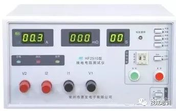
5. Ground Resistance Measuring Instrument
Ground resistance refers to the resistance of the grounding body buried in the ground and the soil dispersion resistance.
Usage Methods
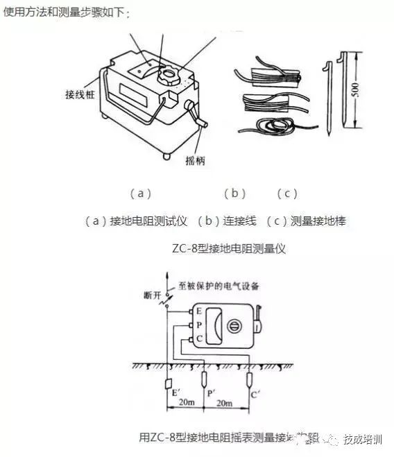
1. Disconnect the connection point between the grounding main line and the grounding body or disconnect all connection points of the grounding branches on the grounding main line.
2. Insert two grounding rods into the ground 400mm deep, one 40m away from the grounding body and the other 20m away from the grounding body.
3. Place the shake meter on a flat area near the grounding body, and then make the connections.
(1) Connect one wire from terminal E of the meter to the grounding body E′.
(2) Connect one wire from terminal C of the meter to the grounding rod C′, which is 40m away from the grounding body.
(3) Connect one wire from terminal P of the meter to the grounding rod P′, which is 20m away from the grounding body.
4. Adjust the coarse adjustment knob based on the required ground resistance of the measured grounding body (there are three adjustable ranges).
5. Shake the meter evenly at a speed of approximately 120 revolutions per minute. When the pointer deflects, adjust the fine-tuning dial until the pointer is centered. The reading set with the fine-tuning dial multiplied by the coarse adjustment positioning multiple gives the measured grounding resistance of the grounding body. For example, if the fine-tuning reading is 0.6 and the coarse adjustment resistance positioning multiple is 10, the measured grounding resistance is 6Ω.
6. To ensure the reliability of the measured grounding resistance value, change the position and re-measure. Take the average of several measured values as the grounding resistance of the grounding body.

Source: Internet
Inheriting Electrical Technology, Advocating Technological Innovation
If you find the content useful, please like and comment!
Welcome to join the Electrical Application WeChat Group ▼