1. Setting the Chip Reference System
(1) Select Program → Teach New Reference System → Teach Chip Reference, and open the “Configure Chip Reference System” dialog box.
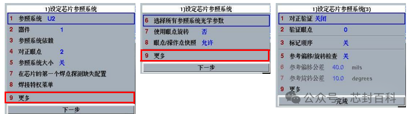
(2) Select More to proceed to the next page. Change parameters as necessary.
(3) Select Finish to complete the configuration of the chip reference system and display the “Chip Operation Point” dialog box.
2. Reference System Dependency
When using Reference System Dependency, it allows the position of the aligned reference system to affect the position of another reference system. For example, when aligning the substrate reference system, the chip and lead reference systems contained within it will move together. Since the operator point, eye point, or lead reference system’s position will remain consistent with the substrate, no alignment is necessary. When teaching the substrate, other reference systems will automatically remain consistent. The reference system dependency function can also be manually set. For example, the chip reference system can be set to depend on the lead reference system. This reduces PRS lookup time.
3. Teaching Chip Operator Points
If the PRS cannot recognize the eye point of the reference system, the machine software will allow manual alignment of the reference system using operator points. Generally, it is required to teach two operator points, which must be located at two clearly visible positions. To adjust the chip rotation, the chip operator points are usually set diagonally opposite each other. The number of taught operator points must match the number of taught eye points. The operator points are located at the upper left and lower right of the chip reference system.
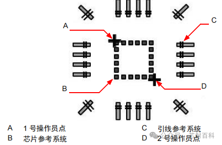
When teaching begins, the status bar on the display will show instructions related to the operating mode, displaying the current functions of buttons B1, B2, and B3.

Teaching Tip: During the teaching operation, you can select the optical system F10 button on the lower function bar or press the F10 button on the MMI (keyboard) to adjust the lighting and magnification as needed. Use F1 to switch between video and graphic displays. Use F2 to zoom out, and use F3 to zoom in.
(1) Select Finish in the “Set Chip Reference System” dialog box to display the “Chip Operation Point” dialog box.
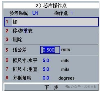
(2) Change the size settings of the operator point teaching box as needed.
(3) Select Add to continue teaching the operator points.
(4) Hold B2 and position the crosshair to the location of the first operator point on the chip.
(5) Press B1 to teach the operator point. Ensure that the indicator in the dialog box reflects the number of the next operator point to be taught. If the operator point teaching is unsuccessful, press B3 to delete and re-teach the program.
(6) Repeat steps (4) and (5) to teach the second operator point.
Note: The line tolerance value can be changed to set the maximum allowable deviation for the teaching distance between the two operator points.
(7) Select Next to end the teaching process and display the “Teach Chip Eye Points” dialog box.
4. Teaching Chip Eye Points
The PRS uses eye points to align the reference system. An example of the chip reference system is as follows, with the teaching steps:
(1) Select Next in the “Operation Point” dialog box to display the “Teach Chip Eye Points” dialog box. Relevant setting information is provided.
(2) Change the size settings of the eye point teaching box as needed.
(3) Select More to proceed to the next page. Change parameters as necessary.
(4) On the first page, select Add to start teaching the eye points.
(5) For the first eye point, hold B2 and position the crosshair to the location on the chip. See the image below:
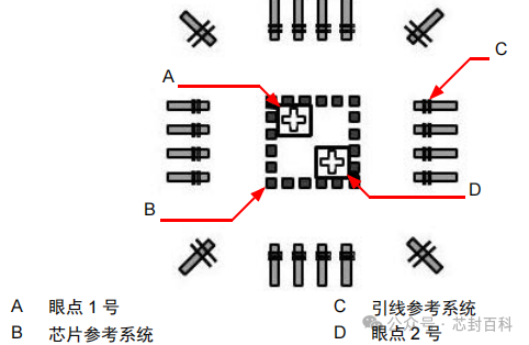
(6) Press B1 to teach the eye point. Ensure that the indicator in the dialog box displays the number of the next eye point to be taught. If the eye point teaching is unsuccessful, press B3 to delete and repeat the teaching program.
(7) Repeat steps (5) and (6) to teach the second eye point.
(8) Select Next to end the teaching process.
Note: Up to 7 backup eye points can be taught so that the PRS can find them when the main eye points are not available. When using backup eye points, the backup eye point parameters in the “Auto Run Settings” menu need to be activated.
5. Automatic Eye Point Teaching
A. Teaching Search Area
When selecting the teaching search area and starting automatic eye point teaching, the following three situations may occur:
(1) If the search area has not been taught, the system will display a prompt dialog:
• You have not taught the search area. Insufficient operator points (less than 2). Select OK and teach a new search area.
• You have not taught the search area. Operator points are (2 or more). Select OK to use the operator points as the search area.
(2) If you need to edit the search area, refer to the mouse functions and the status bar. Add two operator points to the search area, then press B1 to view and swap these operator points.
(3) If you need to set the two operator points for the search area again, press B3 to delete the previous teaching point and press B1 to add new operator points.
B. Automatic Movement Algorithm for Eye Point Search
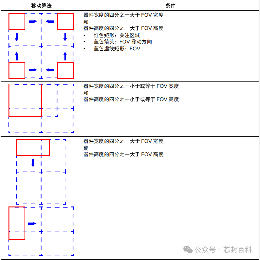
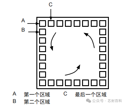
For multiple fields of view (FOV), a movement algorithm can be used for large devices. For small devices, it is not always necessary to move the soldering head to see the next FOV. For large devices, the search will cover one quarter of the device area at a time. See the image below for the movement algorithm for large devices:
C. Automatic Teaching of Main and Backup Eye Points
In automatic mode, there are only two sets of eye points: the main eye point set and the backup eye point set. Information on teaching main and backup eye points for large and small devices is shown in the image below:

6. Configuring Pad Positions
According to actual applications, the physical size of the chip pads can be changed and aligned with different reference systems. (1) From the “Teach Chip Eye Points” dialog box, select Next to display the “Configure Pads” dialog box.
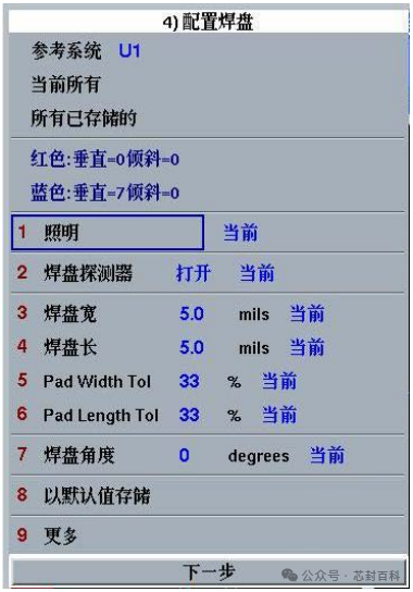
(2) Change parameters as necessary.
(3) Select Next to complete the pad configuration and display the “Teach Chip Soldering Area” dialog box. The options for “Pad Offset” and “Pad Center Offset” will be added to the “Configure Pads” and “Reconfigure Pads” menus to allow teaching of soldering positions outside the center of the chip pads. (4) Go to Teach Process Program → Teach Chip Reference System → Configure Pads (More) menu, and set the values for Pad Offset and Pad Center Offset.
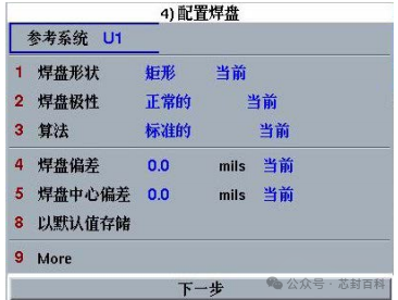

(5) After editing the values of “Pad Offset” and “Pad Center Offset“, re-teach the pads.
(a) At this time, a red cross will be displayed at the soldering position that is not at the center of the pad.
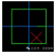
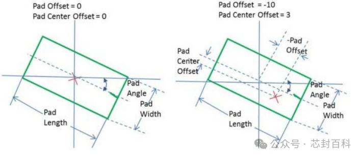
(b) The defined “Pad Offset” and “Pad Center Offset” positions are shown in the image below:
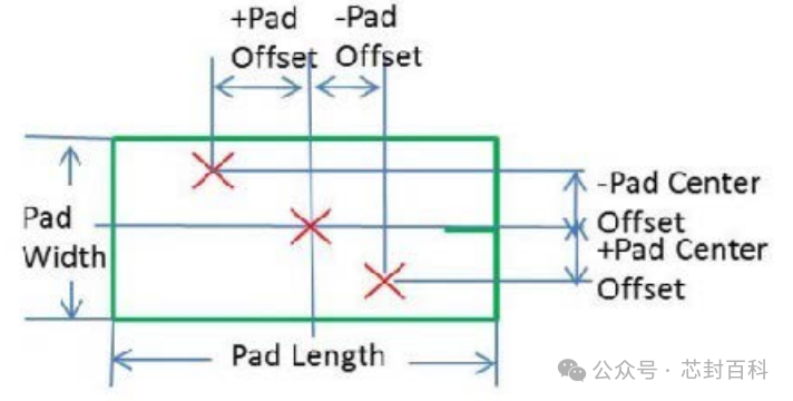
(3) Modify the pad angle. The new pad angle can change the position of the soldering area and recalculate the soldering scan position.
7. Teaching Chip Soldering Area
Through the process of teaching the chip soldering area, the position of the soldering area to be used during soldering can be specified.
Note: In this teaching process, the function of F8 changes from the clamp function to the chip pad rotation function.(1) In the “Configure Pads” dialog box, select Next to display the “Teach Chip Soldering Area” dialog box.
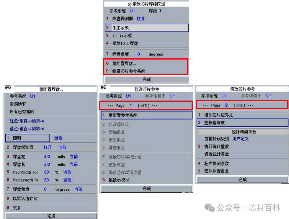
(2) Select Manual Teaching, 1, L Line Teaching or 1, 2, L Pad Teaching to teach the soldering area. (3) Select Next to complete the soldering area teaching and display the “Add Chip Boundary Points” dialog box.
Manual Teaching
The manual teaching option allows for manual teaching of the soldering area for the reference system. This option is most suitable if the areas are not adjacent but are in a row.
Note: You can teach the soldering area in the graphic or video display window.
(1) Select Manual Teaching.
(2) Hold B2 and position the crosshair to the location of the area to be taught.
(3) Press B1 to teach the area. If the area teaching is unsuccessful, press B3 to delete and repeat the teaching process.
(4) Repeat steps (2) and (3) to teach more areas.
(5) Select Finish to complete manual teaching and display the “Add Chip Boundary Points” dialog box.
First Row, Last Row (1, L) Teaching
After teaching the first and last soldering positions in a row, the 1, L line teaching option will allow the software to automatically teach a row of soldering areas. During the teaching process, as long as the row is straight and the soldering areas are evenly spaced, the software can automatically calculate the distance between the grounded soldering areas and teach the entire row area.
(1) Select 1, L Line Teaching.
(2) Hold B2 and position the crosshair to the location of the first area in the row to be taught.
(3) Press B1 to teach the first area in the row.
(4) Hold B2 and position the crosshair to the location of the last area in the row to be taught.
(5) Press B1 to teach the last area in the row.
(6) After teaching the first and last areas, the software will display a dialog box for you to enter the total number of areas in the row. This is the number of pads that need to be soldered in this area, and the spacing between pads must be uniform.
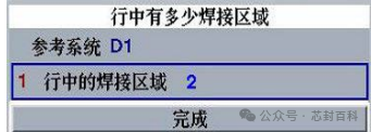
(7) Select Welding area in the row and enter the number of applications for the area.
(8) Select Finish. As long as the row is straight and the soldering areas are evenly spaced, the software can automatically calculate the distance between the grounded soldering areas and teach the entire row area.
(9) After teaching all soldering areas in the row, the “Learning Complete” dialog box will appear. Select OK to continue the operation.
(10) Repeat steps (2) to (9) to teach more row areas.
(11) Select Finish to complete the area teaching and display the “Add Chip Boundary Points” dialog box.
First Pad, Second Pad, Last Pad (1, 2, L) Teaching
After teaching the first pad, second pad, and last pad (1, 2, L), the PRS will teach the complete chip soldering area. The instructions on the status bar guide the complete process of teaching the first, second, and last pad soldering area positions. After teaching the first, second, and last soldering positions, the pad finder software will teach the soldering area to the PRS until there are no more pads. The image below shows how to teach all soldering areas on the chip.
Before using this function, ensure that the pad detector is set to ON, and that the chip pads meet the following conditions:
• All pads are square
• All pad sizes are similar
• All pads have a similar appearance
• All pads have consistent spacing
• All row corners are sharp
• The last soldering area is not the last area in the row, but the last soldering area to be taught
(1) Select 1, 2, L Pad Teaching.
(2) Hold B2 and position the crosshair to the location of the first area to be taught.
(3) Press B1 to change the pad angle value if necessary. If the area teaching is unsuccessful, press B3 to delete and repeat the teaching process.
(4) Hold B2 and position the crosshair to the location of the second area to be taught.
(5) Press B1 to teach the second area. If necessary, change the pad angle value. If the area teaching is unsuccessful, press B3 to delete and repeat the teaching process.
(6) Hold B2 and position the crosshair to the location of the last area to be taught.
(7) Press B1 to teach the last area. If necessary, select the pad angle and enter the applicable pad angle. If the area teaching is unsuccessful, press B3 to delete and repeat the teaching process.
(8) After teaching the last area, the software will automatically teach all remaining areas between the second and last area positions. Once completed, the reading completion dialog box will appear. Select OK and Finish to complete the automatic area teaching and display the add chip boundary points dialog box.
8. Adding Chip Boundary Points
Adding chip boundary points in the chip reference system is generally used for low-arc packaging. Low-arc packaging requires long, low, flat-arc solder wires that do not exceed the top of the groove. To ensure that the soldering machine places the wire arc in the correct position on the solder wire, it is necessary to know the positions of the chip pads and chip boundaries. If boundary points are not set, the soldering machine will set four default boundary points in the process program.
(1) In the “Add Chip Boundary Points” dialog box, select Add.
(2) Hold B2 and position the crosshair to the first boundary point of the chip or the northwest corner.
(3) Press B1 to teach the boundary point. If necessary, press F2 to zoom in, and press F3 to zoom out.
(4) Teach the boundary points in the following order: Northwest, Southeast, Northeast, Southwest; after teaching one boundary, the machine will jump to the next boundary.
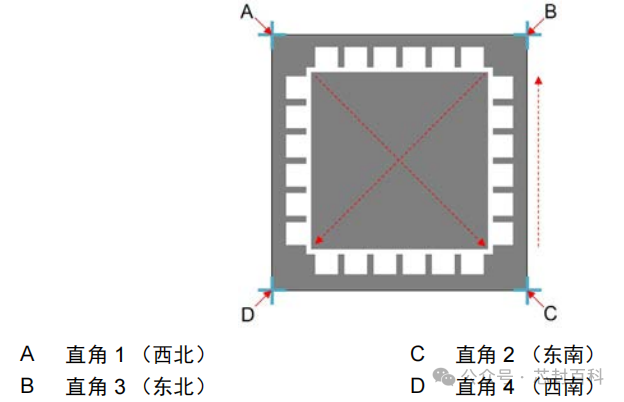
(5) After teaching all four boundary points, select Finish.