The editor has shared an article titled “Where Does the Greatest Sense of Achievement Come from as an Electrical Engineer?” which has garnered much attention from netizens. Today, we are sharing another article by Teacher Zhang, discussing the topic of “How to Learn PLC” in hopes that everyone can find inspiration from it.
PLC is Not Difficult to Learn
First, the PLC programming language must comply with the IEC 61131 standard, with the most mainstream language being the modular programming language, specifically the IEC 61131-3 language. Since all PLC manufacturers must adhere to the IEC 61131 standard, once you deeply learn one PLC, others are generally similar.
In school, PLC textbooks typically explain using ladder diagrams. This is a rather outdated programming method. Once you enter the workforce, you must switch to modular programming methods.
The reason for abandoning ladder diagram programming is mainly due to its many limitations. For example, when three switch quantities form a triangle on a ladder diagram, this ladder diagram cannot be executed; it must be converted into a star structure using a triangle-star conversion. Such issues do not arise in modular programming languages. Due to the limitations of ladder diagrams, pure ladder diagram programs have also started to incorporate modular diagrams.
The following image shows a partial program I wrote for the dual power automatic switching system in the environmental control power distribution room of a subway station in Beijing:
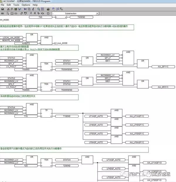
(Click the image to enlarge)
This program is written in the modular programming language IEC 61131-3. It can be seen that modular PLC programs are somewhat similar to integrated circuits, and even PID control has corresponding modules.
Next, let’s take a look at the communication management part of the same program:
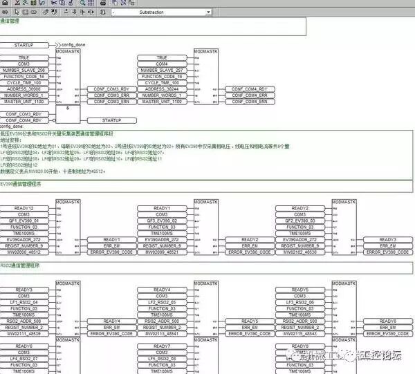
(Click the image to enlarge)
Here, there are communication interface initialization programs, MODBUS-RTU master station definition programs, and MODBUS-RTU slave data collection and exchange loop programs.
It is evident that modular PLC programming languages are worlds apart from the ladder diagram programming languages learned in school.
Since PLC programming languages support software-level program debugging, simulation is not a significant issue.
Second, in addition to having a programming environment, it is also necessary to have engineering examples. In fact, engineering examples are easy to obtain; we can find any book that describes motor control and write all the various methods of controlling motors, of course using relays and contactors, into PLC control methods. After completing a few examples, you will basically understand it. After finishing the examples, increase the difficulty for yourself. For instance, imagine having four motors, serving as the central air conditioning cold water unit, hot water unit, cooling tower motor, and paired with the fan of the terminal air conditioning device, forming a complete central air conditioning system. The central air conditioning uses enthalpy control and PID regulation. Try to use PLC as the central control system to write a program.
Once this example is completed, finally learn about PLC communication technology. Pay special attention to the MODBUS-RTU module in the modular programming language of PLC, understand its content and essentials, and then write a data collection and forwarding system. The data sources are the peripheral switch quantities, temperature quantities, enthalpy values, current and voltage parameters, motor operating states, etc., from all the motors in the previous example. Write these parameters into a communication protocol, i.e., a data point table, and then send it to the ACCESS database on the computer. Using ACCESS’s VBA, write several control interfaces to achieve information exchange and control in software.
Once all of this is completed, you can graduate. From then on, you will be capable of handling any PLC programming work.
PLC applications are extremely widespread. In industrial environments, PLCs are almost omnipotent. Do you know why?
First, PLCs have high reliability: because their programs are executed sequentially, they will not enter dead loops and almost never crash.
The fact that PLCs do not crash is very important.
We originally used industrial computers as communication management machines for measurement and control and power distribution systems. However, we found that the hard drives of industrial computers would fail at high temperatures, and if the fan stopped running, the power supply would quickly shut down due to overheating (crashing), causing communication interruptions. Industrial computers rely on various cards to achieve data collection and control functions, and these cards have a high failure rate. Achieving hardware redundancy in industrial computers is very difficult, while PLC’s CPU hardware redundancy is very convenient. After replacing the communication management machine in our measurement and control projects with PLCs, these issues were completely and perfectly resolved.
Second, PLCs have a high level of EMC (Electromagnetic Compatibility), meaning they have strong anti-interference capabilities. EMC refers to the ability of electrical components to resist environmental electromagnetic interference during operation and the degree to which they generate electromagnetic interference in the environment. IEC and national standards impose mandatory EMC testing requirements on electrical components and control cabinets. High-end PLCs generally need to pass level 2 to level 3 EMC group pulse tests and grounding current impact tests.
I have tested a multifunctional power meter’s circuit board, and just because the power supply filter capacitor was soldered slightly too high, the entire circuit board was destroyed during the grounding current impact test. This shows that EMC testing is extremely harsh for electronic instruments, and passing the tests is not easy.
In short: whatever a microcontroller can do, a PLC can certainly do; conversely, what a PLC can do, a microcontroller may not be able to do, or may not even come close.
For comparison: it is somewhat difficult for general household appliances to pass level 1 EMC tests.
Due to the extensive applications of PLCs, a senior and excellent PLC programmer is also a versatile industrial system expert. They are familiar with the performance parameters of components and sensors under various industrial conditions, the principles of measurement and control and automatic control under various industrial conditions, the mechanical principles, and various industrial process flows, and know how to select components and switches under strong electromagnetic environments. Of course, this person should also be very familiar with PLC modules.
In summary, an excellent PLC programmer is also a technical leader.
At the beginning of learning, do not always think about making money; focus on learning real skills. The world is vast; where can you not find good opportunities? The money earned by PLC salespeople is far less than that earned by PLC programmers; after the project is completed, users remember the programmers, not the PLC salespeople; in subsequent projects, they will invite programmers to continue participating, while PLC salespeople will only supply a few PLCs at most.
Conclusion: The key still lies in your programming skills and technical level.
Netizen: Is the PLC CPU also a microprocessor?
Answer: Of course, but the structural design and circuit design of PLCs are developed under EMC anti-interference conditions, so they have extremely strong anti-interference capabilities.
In the R&D center, after the circuit board design is completed, all components, including the CPU, are soldered onto it, and the lengths of the component pins and the heights of the components must meet specifications. Then, the circuit board is installed into a specially designed shell, connected to peripheral circuits, and simulated in actual working scenarios. The EMC tester is turned on, and the corresponding EMC interference group pulses are input from the power supply end, or EMC grounding currents are input from the grounding point. At this point, if there is a problem with the components, the circuit board will be immediately destroyed.
During testing, the differences between industrial-grade and consumer-grade components can be clearly seen, as well as whether the circuit board design is reasonable, whether the component pairing and installation heights meet the electromagnetic field distribution requirements, and whether the electromagnetic isolation of the forward channel is complete, etc.
Generally, EMC testing is conducted multiple times. From the first EMC test to the final pass, the circuit board has been modified beyond recognition, and the working principles of the circuit will also be modified and adjusted accordingly.
After the laboratory EMC testing is completed, functional testing and adjustments are performed. Once everything is completed, the complete PLC is sent to the national designated testing center for type testing. This process also requires multiple iterations. Once the type testing is passed, the product is qualified for market sales, and small-scale production begins.
The production process often involves component adjustments. A good design meets production requirements, has a reasonable structure, and good repeatability. If the process and component parameters do not meet production requirements, the corresponding parts of the product must be adjusted. If component replacement is involved, EMC testing and performance testing must be conducted again.
It can be seen that from the proposal of the design concept to the production of the product for market provision, there are many paths to take. This is fundamentally different from simply demonstrating functionality with a circuit board in school.
Once the product is on the market, adjustments to various parameters are needed based on the product’s performance under various working conditions, forming different specifications and grades of the product.
The sweet and sour experiences in this process are known only to the designers themselves.
In summary, for electrical products used under industrial conditions, EMC testing is the most important. EMC greatly enhances the product’s anti-interference capability, improves its functionality and application range, and plays a crucial role.
Regarding EMC, IEC has many standards for regulation, and our national standards also have corresponding provisions. Specific standards can be referenced.
Netizen: The statement “What PLC can do, industrial computers may not be able to do” seems a bit biased, right?
Originally, the underlying principles are completely the same; it’s just an EMC issue. Just like LABVIEW has launched a series of hardware suitable for industrial control, it seems that PLC does not have much of an advantage. For example, aircraft and spacecraft also often use industrial computers or various embedded systems, but the hardware requirements are more reliable and robust. I believe the biggest advantage of PLC lies in its efficient and reliable development; anyone following strict standards can achieve a highly reliable system.
Answer: That’s right: it depends on the working conditions. Our communication management machines are installed in high-voltage, medium-voltage, and low-voltage switchgear sites. Especially in low-voltage and medium-voltage switchgear, they are directly installed inside the cabinets.
The temperature inside the cabinets is very high, about 40 degrees. The electromagnetic field strength inside the cabinets is also significant. Plus, there is dust. The power supply fans, CPU fans, and the entire circuit board become heavy casualties. Fans often stop running due to severe dust contamination, leading to the entire machine shutting down or even burning out the CPU.
The industrial computer installed inside the switchgear must run continuously without downtime during two maintenance periods. We have equipped it with dual-machine redundancy technology, but since both machines must be powered on, the aforementioned issues remain serious.
Since switching to PLCs, this passive situation has been completely changed.
As for industrial computers installed indoors, their working conditions are much better, so it is not necessarily required to replace them with PLCs.
In summary, whether for communication management machines used in industrial control sites or for communication management machines used in power monitoring sites, at ABB, we have replaced industrial computers with PLCs.
Additionally, PLC redundancy comes in two forms: logical redundancy and hardware redundancy. Logical redundancy refers to two independent PLCs that are interconnected and monitor each other using handshake lines. If the master has a problem, the slave immediately takes over, but the time may take several hundred milliseconds; hardware redundancy refers to the same PLC having two CPUs installed, both of which operate synchronously according to the clock. When the main CPU has a problem, the backup CPU can take over within a few clock cycles. Therefore, hardware redundancy switching is faster.
However, even with logical redundancy, the switching speed far exceeds that of industrial computers. This is one of the main reasons we ultimately chose PLCs.
Tip 1: About Maintenance Periods
The two maintenance periods are generally two years. The maintenance period is related to the importance of the power distribution equipment. For example, for a substation supplying power to a certain urban area, maintenance requires power outages, which has a significant impact, necessitating careful arrangements by the power distribution network. For example, in factories, many devices cannot be powered off (similar to glass melting kilns, flow control, etc.), and the maintenance period for power distribution equipment is also long.
Regardless of the type of power distribution or control equipment, close monitoring of the switchgear or control cabinet is required, which is the main purpose of using PLCs as communication management machines, along with various measuring instruments, relay protection devices, and control devices. People can judge the operating status of the equipment inside the cabinet based on the collected information, thus deciding whether maintenance is needed.
Tip 2: About the Working Environment Inside the Switchgear
The electromagnetic interference inside the switchgear is extremely strong. We have conducted experiments using ordinary microcontroller circuit boards (without external protective boxes, completely exposed) placed inside, and after powering on, just breaking a circuit breaker once caused the microcontroller to be destroyed. Subsequently, using an industrial computer, the situation improved significantly, but strong arcs can still cause failures in the industrial computer. Additionally, the connectors of industrial computers are a major issue; after a while, many card connections fail. The reason is due to dust and high temperatures.
Speaking of dust, we find it strange that switchgear particularly attracts dust. Perhaps it is due to the higher voltage.
To prevent dust and water, IEC has specified IP protection levels. Therefore, many power distribution devices have high protection levels, but the side effect is that the temperature inside the cabinets is higher, requiring not only the switchgear itself to be derated, but also various power instruments, including communication management machines, to be easily damaged due to high temperatures.
Altitude also has a certain impact. In plateau areas, due to strong ultraviolet rays, the number of charged particles in the air increases, making it difficult to extinguish arcs once they occur. Inside the switchgear, even a relay switch can produce a stronger arc than in plain areas. These factors also affect various electronic devices.
Therefore, in plateau areas, such as the 110kV substations along the Qinghai-Tibet Railway, we absolutely do not use industrial computers as communication management machines.
Netizen: Ladder diagrams are a very outdated programming method, which is quite amusing. Programming has its techniques; no language is superior or inferior.
Answer: Wrong.
Ladder diagrams belong to the IEC 61131-1 programming language. Due to their limitations, they must incorporate a large number of modules, namely IEC 61131-3 programming modules, such as communication modules, PID modules, switch quantity to word modules, etc. In other words, IEC 61131-1 can no longer stand alone and must rely on IEC 61131-3 to assist in programming.
Since this is the case, why not directly use the IEC 61131-3 programming language?
Because ladder diagrams are simple and intuitive, they are very suitable for students to learn. However, in actual programming, if one still clings to ladder diagrams, it appears particularly uncoordinated.
From the perspective of PLC products, most PLCs produced by Europe, the United States, and Japan’s Mitsubishi adopt the IEC 61131-3 programming language, while Japan’s Omron PLCs and domestic PLCs use a mix of IEC 61131-1 and some IEC 61131-3 modules. ABB’s high-end PLCs used for DCS measurement and control have completely abandoned the IEC 61131-1, i.e., ladder diagram programming method.
Thus, it can be seen that modular programming languages are the mainstream direction of PLC programming.
For example, in IEC 61131-3, PID has already become a module, and programmers only need to complete the PID parameters to obtain the final control output. In contrast, ladder diagrams are not only cumbersome but also require many so-called techniques. Comparing the two, the advantages and disadvantages are clear.
Netizen: Ladder diagrams are also a standard language of IEC61131-3, right?
Answer: Yes, I have also noticed that the latest IEC61131-3 standard has merged ladder diagrams and modular diagrams together. I have also asked members of the IEC standards committee. They replied that ladder diagrams are used too widely, and it is necessary to merge these two drawing methods.
It feels like one must look at issues comprehensively; perhaps what was previously overlooked has now become popular.
Similar phenomena also exist: field buses and 4~20 mA information collection systems. Initially, it was said that the former would definitely eliminate the latter, but now they are integrating with each other.
There is also the three-phase four-wire system and the three-phase five-wire system. IEC originally scoffed at the three-phase five-wire system, but now it is discussing the recognition of the three-phase five-wire system. The speed of change seems to be faster than us taking off our clothes (laughs).
Source: Mechanical Industry Press E-View界(WeChat: tz043010120)
Submission email: [email protected]. Accepted submissions will receive a fee!
—————–End—————-
Long press the QR code to follow the forum master