
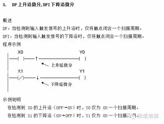
When the trigger signal state changes from OFF to ON, the DF instruction is executed, and the output is only activated for one scan cycle.
When the trigger signal state changes from ON to OFF, the DFI instruction is executed, and the output is only activated for one scan cycle.
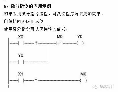
If the execution condition is initially closed, the PLC will not produce an output when powered on. Programming considerations.
The usage of DF and DFI instructions is limited; the total number of times these two instructions can be used in CX1-16R is a maximum of 128 times.
8. Try to draw a simple ladder diagram: The drawing of a simple ladder diagram is generally based on existing electrical schematic diagrams, drawn according to their working principles, progressing from simple to complex, first aiming for clarity, and gradually understanding the insights of drawing ladder diagrams. First, one must understand the working principle of the electrical schematic, and then draw according to the requirements of the PLC. It is important to note that one should not simply correspond each PLC contact with each contact on the electrical schematic (this is a common mistake among beginners); if this is done, it may lead to a dead end, and the ladder diagram should only achieve its intended purpose.
① Non-reversible start should be controlled by PLC
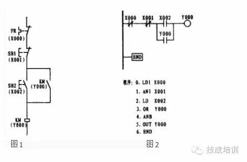
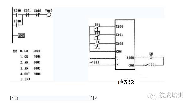
The above figure 1 is the electrical schematic, while figure 2 is the ladder diagram drawn according to the principle of one-to-one correspondence with the schematic. Its characteristic is that it is easy to understand, but in my experience, there are not many that can be drawn this way. If this method is used for drawing, it may lead to a point of no return. Although both diagrams can operate, if figure 2 is modified to become figure 3, it can be seen that figure 3 lacks a step sequence ANB in the program. Clarity and simplicity are essential elements of programming. Therefore, when drawing ladder diagrams, one should try to place multiple contacts in parallel on one side of the ladder diagram to reduce the ANB instruction. The X000 in figure 2 and the X002 in figure 3 are both normally closed contacts controlled by external thermal relays, while the thermal relay uses normally open contacts (or the normally closed contacts of the external thermal relay can be connected in series with the contactor coil). Only after drawing the ladder diagram should the program be compiled based on the ladder diagram.
Source: Provided by Liu Wen, a student from the 3351st issue of Technical Achievement!
Must-read to enhance your knowledge 
Click to read the original text,and learn more about electrical engineering, PLC, and CNC robotics for free
↓↓↓