1
Data Types
1. Word Length
The storage units of the S7-200 SMART PLC (i.e., programming components) store data in binary form. The length of data is referred to as word length, which can be classified into bits (1 bit binary, represented as b), bytes (8 bits binary, represented as B), words (16 bits binary, represented as W), and double words (32 bits binary, represented as D).
2. Types and Ranges of Data
The data types stored in the storage units of the S7-200 SMART PLC can be divided into Boolean, integer, and real number (floating-point) types.
1) BooleanBoolean data consists of 1 bit, also known as bit type, used to represent two different states of a switch (or digital quantity). When a programming component is 1, it is referred to as the 1 state, or the component is in the ON state, and the corresponding coil is “powered on,” with normally open contacts closing and normally closed contacts opening; when the component is 0, it is referred to as the 0 state, or the component is in the OFF state, and the corresponding coil is “de-energized,” with normally open contacts opening and normally closed contacts closing. For example, the data of output relay Q0.0 is of Boolean type.2) Integer
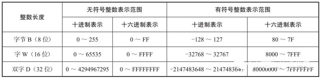
Integer data does not have a decimal point, and it is divided into unsigned integers and signed integers. Signed integers require 1 highest bit to represent the sign of the data, typically with the highest bit of 0 indicating a positive number and 1 indicating a negative number. Table 1 lists the value ranges represented by integers of different word lengths.
Table 1 Value Ranges Represented by Integers of Different Word Lengths
3) Real Numbers
Real number data, also known as floating-point data, is a type of data that includes a decimal point. It uses 32 bits to represent (i.e., word length is double word), and its data range is very large, with positive numbers ranging from +1.175495E-38 to +3.402823E+38 and negative numbers ranging from -1.175495E-38 to -3.402823E+38.
3. Programming Format for Constants
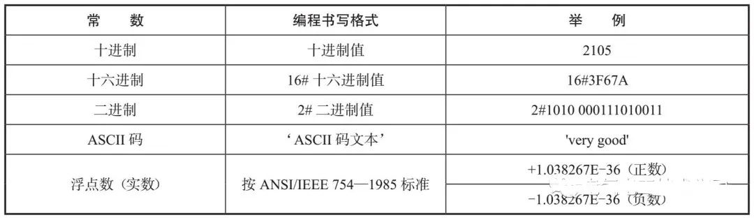
Constants are frequently used in programming. The length of constants can be bytes, words, or double words. Constants are also stored in binary form in the PLC, but during programming, constants can be written in decimal, hexadecimal, binary, ASCII code, or floating-point (real number) form, which are then automatically compiled into binary numbers by the programming software and downloaded to the PLC.
The programming format for constants is shown in Table 2.
Table 2 Programming Format for Constants
2
Addressing Methods
In the S7-200 SMART PLC, data is stored in memory. For ease of access, each memory unit must be addressed. When accessing data, simply locating the address of a unit allows for data retrieval. The addressing methods of the S7-200 PLC are mainly divided into two types: direct addressing and indirect addressing.
1. Direct Addressing
1) Addressing
To understand the addressing method of the memory, one must first grasp its addressing rules. The storage units of the S7-200 SMART PLC are systematically divided into several areas based on functionality, such as I area (input relay area), Q area (output relay area), M area, SM area, V area, L area, etc. Since each area contains many storage units, these units need to be addressed. PLC storage areas commonly adopt the following addressing methods.
① I, Q, M, SM, and S areas are addressed in bit order, such as I0.0 to I15.7, M0.0 to M1.7.
② V and L areas are addressed in byte order, such as VB0 to VB2047, LB0 to LB63.
③ AI and AQ areas are addressed in word order, such as AIW0 to AIW30, AQW0 to AQW30.
④ T, C, HC, and AC areas are directly addressed by number size, such as T0 to T255, C0 to C255, AC0 to AC3.
2) Direct Addressing Method
Direct addressing finds the unit by directly specifying the area, length, and position of the storage unit to be accessed. The direct addressing methods of the S7-200 SMART PLC are mainly:
① Bit addressing. The format for bit addressing is: Bit Unit Addressing = Storage Area Name (Component Name) + Byte Address.Bit addressFor example, if the address I2.3 is given for addressing, the address to be found is the 3rd bit of the 2nd byte in the I storage area, as shown in Figure 1.
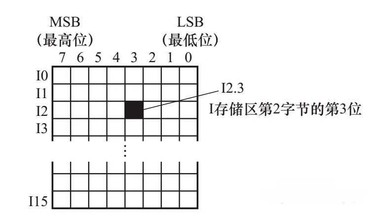
Figure 1 Example of Bit Addressing
The storage areas that can perform bit addressing include I, Q, M, SM, L, V, and S. Byte/word/double word addressing.
② Byte/word/double word addressing is performed as units of bytes, words, or double words, Addressing format is:
Byte/Word/Double Word Addressing = Storage Area Name (Component Name) + Word Length (Byte, Word, or Double Word) + Starting Byte Address
For example, if VB100 is given for addressing, the address to be found is the 100th byte in the V storage area; if VW100 is given, the address to be found is the 100th and 101st bytes in the V storage area; if VD100 is given, the address to be found is the 100th to 103rd bytes in the V storage area. The relationship between VB100, VW100, and VD100 is shown in Figure 2, where VW100 consists of VB100 and VB101, and VD100 consists of VB100 to VB103. When the VW100 unit stores a 16-bit binary number, VB100 stores the high byte (high 8 bits), and VB101 stores the low byte (low 8 bits); when the VD100 unit stores a 32-bit binary number, VB100 stores the highest byte, and VB103 stores the lowest byte.
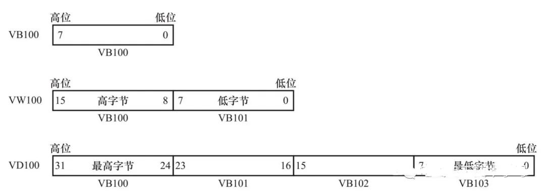
Figure 2 Relationship Between VB100, VW100, and VD100
Storage areas that can perform byte addressing include I, Q, M, SM, L, V, AC (only low 8 bits), and constants; storage areas that can perform word addressing include I, Q, M, SM, L, V, T, C, AC (only low 16 bits), and constants; storage areas that can perform double word addressing include I, Q, M, SM, L, V, AC (32 bits), and constants.
2.Indirect Addressing
Indirect addressing means that the address of the unit to be accessed is not directly given, but stored in some special storage units. This special storage unit used to store the address is called a pointer, which can only be undertaken by V, L, or AC (accumulator). Using indirect addressing is very convenient when accessing data in continuous addresses, making programming very flexible.
Indirect addressing generally involves three processes: establishing a pointer, accessing data using the pointer, and modifying the pointer.
1) Establishing a Pointer
To establish a pointer, the double word transfer instruction (MOVD) must be used to store the address of the unit to be accessed into the pointer (the special storage unit used to store the address). An example of establishing a pointer is as follows.
MOVD &VB200, AC1 // Store the address of storage unit VB200 into accumulator AC1. The “&” before the operand in the instruction is the address symbol, and “&VB200” indicates the address of VB200 (not the data stored in VB200). The “//” is the comment symbol, and the text following it is used to annotate the instruction, which the software will not compile. When establishing a pointer, the word length of the second operand in the instruction must be a double word storage unit, such as AC, VD, or LD.
2) Accessing Data Using the Pointer
Once the pointer is established, it can be used to access data. An example is as follows.
MOVD &VB200, AC0 // Establish pointer, store the address of storage unit VB200 into accumulator AC0
MOVW *AC0, AC1 // Use the address in AC0 (address of VB200) as the starting address to store the data from the two consecutive bytes (one word, i.e., VB200, VB201) into AC1
MOVD *AC0, AC1 // Use the address in AC0 (address of VB200) as the starting address to store the data from the four consecutive bytes (double word, i.e., VB200 to VB203) into AC1
The “*” before the operand in the instruction indicates that the operand is a pointer (a storage unit containing an address). The execution process of the above instructions is illustrated in Figure 3.
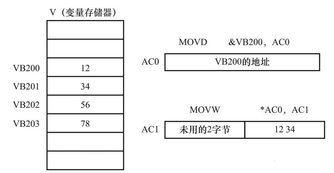
Figure 3 Indirect Addressing Illustration
The result of executing the “MOVD &VB200, AC0” instruction is that the address of storage unit VB200 is stored in AC0; the result of executing the “MOVW *AC0, AC1” instruction is that using the VB200 address in AC0 as the starting address, the data from the two consecutive byte units (VB200, VB201) is stored in AC1. If the data in units VB200 and VB201 are 12 and 34, respectively, after executing this instruction, the low 16 bits of AC1 will contain “1234”; the result of executing the “MOVD *AC0, AC1” instruction is that using the VB200 address in AC0 as the starting address, the data from the four consecutive byte units (VB200 to VB203) is stored in AC1, and after executing this instruction, AC1 will contain “12345678”.
3) Modifying the Pointer
The word length of the pointer (the special storage unit used to store the address) is a double word (32 bits), and modifying the pointer value requires using double word instructions. Common double word instructions include double word addition instruction (ADDD) and double word increment instruction (INCD). When modifying the pointer value and accessing bytes, the pointer value is incremented by 1; when accessing words, the pointer value is incremented by 2; when accessing double words, the pointer value is incremented by 4. An example of modifying the pointer value is as follows.
MOVD &VB200, AC0 // Establish pointer
INCD AC0 // Increment the value in AC0 (i.e., increment the address value by 1)
INCD AC0 // Increment the address value in AC0 again
MOVW *AC0, AC1 // Read pointer
Using the new address in AC0 as the starting address, store the data from the corresponding two consecutive byte units into AC1.
For example, the result of executing the above program is that using the address of unit VB202 in AC0 as the starting address, the data 56 and 78 from units VB202 and VB203 are stored in the low 16 bits of AC1.
Disclaimer: This article is shared from the internet, and the copyright belongs to the original author. If there are any copyright issues, please contact us promptly for deletion. Thank you!

Get Electrical Software for Free
Scan the QR code below↓↓↓to get it “for free“!