For beginners, electromagnetic interference (EMI) in microcontroller circuit design may not be a primary concern, but for an electronic engineer, the implications are significant. It not only affects the microcontroller’s ability and accuracy in control but also impacts the company’s competitiveness in the industry.
We primarily address EMI design from both hardware and software perspectives. Below, we will discuss how to handle electromagnetic compatibility (EMC) from PCB design to software processing.
Factors Affecting EMC
1. Voltage
A higher power supply voltage means a larger voltage amplitude, resulting in more emissions, while a lower power supply voltage affects sensitivity.
2. Frequency
High frequencies generate more emissions, and periodic signals produce more emissions. In high-frequency microcontroller systems, current spikes occur when devices switch; in analog systems, current spikes occur when load currents change.
3. Grounding
Among all EMC issues, improper grounding is a major concern.
There are three grounding methods:
-
Single-point, multi-point, and hybrid. Single-point grounding can be used at frequencies below 1 MHz but is not suitable for high frequencies;
-
In high-frequency applications, multi-point grounding is preferred;
-
Hybrid grounding uses single-point grounding for low frequencies and multi-point grounding for high frequencies. Ground layout is critical; the grounding circuits for high-frequency digital circuits and low-level analog circuits must not be mixed.
4. PCB Design
Proper PCB layout is crucial for preventing EMI.
5. Power Decoupling
When devices switch, transient currents are generated on the power lines, which must be attenuated and filtered out.
Transient currents from high di/dt sources cause ground and trace “emission” voltages; high di/dt generates a wide range of high-frequency currents, exciting components and cables to radiate.
Changes in current flowing through wires and inductance can cause voltage drops; reducing inductance or the rate of current change can minimize this voltage drop.
Hardware Measures for Interference Mitigation
1. Electromagnetic Compatibility Design of Printed Circuit Boards (PCBs)
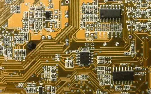
PCBs are the support for circuit components and devices in microcontroller systems, providing electrical connections between them. With the rapid development of electronic technology, PCB density is increasing.
The quality of PCB design significantly impacts the electromagnetic compatibility of microcontroller systems. Practice has shown that even if the circuit schematic is designed correctly, improper PCB design can adversely affect the reliability of the microcontroller system.
For example, if two thin parallel lines on a PCB are too close, they can cause signal waveform delays and reflection noise at the transmission line’s termination.
Therefore, when designing PCBs, it is essential to adopt correct methods, adhere to general PCB design principles, and meet anti-interference design requirements. The layout of components and routing of traces are crucial for optimal electronic circuit performance.
2. Electromagnetic Compatibility Design of Input/Output
In microcontroller systems, inputs/outputs also serve as conductive lines for interference sources and as detection sources for receiving radio frequency interference signals. We generally take effective measures during design:
① Implement necessary common-mode/differential-mode suppression circuits, and also take certain filtering and electromagnetic shielding measures to reduce interference.
② Where conditions permit, various isolation measures (such as opto-isolation or magnetic isolation) should be taken to block the propagation of interference.
3. Design of Microcontroller Reset Circuits
In microcontroller systems, the watchdog system plays a particularly important role in the operation of the entire microcontroller. Since not all interference sources can be isolated or eliminated, once interference enters the CPU, the reset system combined with software measures becomes an effective error correction defense barrier.
Common reset systems include the following two types:
① External reset systems. External “watchdog” circuits can be designed by oneself or built using dedicated “watchdog” chips.
However, they each have their pros and cons. Most dedicated “watchdog” chips do not respond to low-frequency “feeding” signals, while they respond to high-frequency “feeding” signals, causing a reset action under low-frequency signals but not under high-frequency signals. Thus, if the program system gets stuck in a loop that coincidentally includes a “feeding” signal, the reset circuit will fail to perform its intended function.
However, we can design a system with a band-pass “feeding” circuit and other reset circuits, which would be an effective external monitoring system.
② More and more microcontrollers now come with their own on-chip reset systems, allowing users to conveniently use their internal reset timers. However, some microcontroller models have overly simplistic reset instructions, which can lead to issues similar to the aforementioned loop, where the “feeding” instruction loses its monitoring function.
Some microcontroller on-chip reset instructions are well-designed, generally formatting the “feeding” signal into a fixed sequence of multiple instructions. If an error occurs, the “feeding” operation becomes ineffective, greatly improving the reliability of the reset circuit.
4. Oscillator
Most microcontrollers have an oscillator circuit coupled to external crystals or ceramic resonators. On the PCB, the leads for external capacitors, crystals, or ceramic resonators should be as short as possible.
RC oscillators are inherently sensitive to interference signals and can produce very short clock cycles, so it is best to choose crystals or ceramic resonators. Additionally, the quartz crystal’s casing should be grounded.
5. Lightning Protection Measures
Microcontroller systems used outdoors or power and signal lines introduced from outdoors must consider lightning protection issues. Common lightning protection devices include gas discharge tubes, TVS (Transient Voltage Suppression), etc.
Gas discharge tubes conduct when the voltage exceeds a certain value, typically several tens or hundreds of volts, allowing strong surge pulses to be directed into the ground.
TVS can be viewed as two Zener diodes connected in parallel and in opposite directions, which conduct when the voltage across them exceeds a certain value. They can momentarily carry hundreds to thousands of amps of current.
Software Measures for Interference Mitigation
Interference signals generated by electromagnetic interference sources cannot be completely eliminated under certain conditions (such as in harsh electromagnetic environments) and will ultimately enter the core unit of the CPU. In such cases, large-scale integrated circuits often suffer interference, leading to abnormal operation or operation in an erroneous state.
Especially for devices like RAM that use bistable storage, strong interference can cause bit flips, changing stored “0” to “1” or “1” to “0”; some serial transmission timing and data may change due to interference; more seriously, important data parameters may be corrupted, leading to severe consequences.
In such cases, the quality of software design directly affects the system’s ability to resist interference.
1. Programs may experience several types of issues due to electromagnetic interference:
① Program runaway.
This is the most common result of interference. Generally, a good reset system or software frame measurement system can mitigate the impact on the overall operating system.
② Infinite loops or abnormal program code execution.
Of course, these infinite loops and abnormal program codes are not intentionally written by the design staff. We know that program instructions are composed of bytes, some being single-byte instructions and others multi-byte instructions. When interference occurs, it can cause the PC pointer to change, leading to the original program code being reorganized into unpredictable executable code.
This type of error is critical; it may modify important data parameters or produce unpredictable control outputs, leading to a series of erroneous states.
2. Measures for Storing Important Parameters
In general, we can use error detection and correction to effectively reduce or avoid such situations.
According to the principles of error detection and correction, the main idea is to generate a fixed number of check codes based on the data being written and store them along with the corresponding data; when reading, the check code is also read and evaluated.
If a single-bit error occurs, it is automatically corrected, and the correct data is sent out, while the corrected data overwrites the original erroneous data; if two-bit errors occur, an interrupt report is generated, notifying the CPU for exception handling.
All these actions are automatically completed by software design, characterized by real-time and automatic execution. Through such design, the system’s ability to resist interference can be significantly improved, thereby enhancing the system’s reliability.
Principles of Error Detection and Correction:
-
First, let’s look at the basic principles of error detection and correction. The fundamental idea of error control is to add different types of redundant codes to the information code group according to certain rules, so that when the information is read out, errors can be detected or automatically corrected using the extra monitoring codes or check codes.
-
Given the characteristics of error occurrence, namely the randomness and small probability of errors, they almost always randomly affect a specific bit in a byte. Therefore, if we can design a system that automatically corrects single-bit errors while checking for two-bit errors, we can greatly enhance the system’s reliability.
3. Testing RAM and FLASH (ROM)
When programming, it is best to write some test programs to check the data codes in RAM and FLASH (ROM) for errors. If errors occur, they should be corrected immediately, and if they cannot be corrected, an error indication should be provided to the user for handling.
Additionally, incorporating redundancy into the program is essential. Adding three or more NOP instructions at certain points can effectively prevent program reorganization.
At the same time, during program operation, it is important to introduce flag data and detection states to promptly identify and correct errors.


Screenshots of Selected Electronic Books

Screenshots of Selected Courseware PPTs

【Complete Set of Hardware Learning Materials】