ARM defines two low-power interfaces for low power control handshakes, namely Q-Channel and P-Channel. The Q-Channel was discussed previously in “SoC Design Power Consumption – Q Channel“. The Q-Channel is relatively simpler than the P-Channel, as it only controls two states: on and off. This is fine for handshakes controlling clocks, but insufficient for handshakes controlling power. For a complex design, merely describing with on/off states is incomplete; more power states need to be introduced, such as memory retention (a low-power technique that provides a lower supply voltage to memory cells to retain the data in the storage array, while the memory cells do not accept external data access).
The P-Channel introduces a concept called power state transition. In the application scenarios of the P-Channel, there are many power states which can be user-defined. The various states of power can be switched between each other.
The P-Channel interface is not complex:
-
N-bit PACTIVE, driven by the device side, where each bit may consist of multiple source signals;
-
M-bit PSTATE, driven by the controller side, indicating the requested power state to transition to;
-
PREQ, driven by the controller side, high level indicates a request to transition to a power state (the power state is defined by PSTATE);
-
PACCEPT, driven by the device side, high level indicates that the device accepts the power state transition request issued by the controller;
-
PDENY, driven by the device side, high level indicates that the device denies the power state transition request issued by the controller;
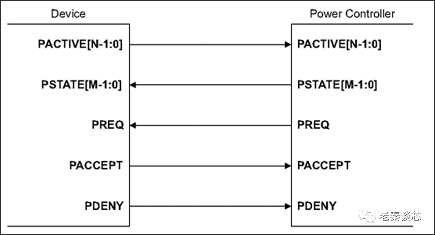
The values of N and M depend on specific design needs; the P-Channel specification does not enforce any requirements.
PREQ, PACCEPT, and PDENY form a handshake interface (PACTIVE is not involved in the handshake) to manage and ensure safe state transitions. The P-Channel requires that in a single handshake transition, only one of PACCEPT or PDENY can change. In other words, during the handshake, only one of PACCEPT and PDENY can be high.
The PACCEPT and PDENY signals from the device, as well as the PREQ and PSTATE signals from the controller, must be driven directly by registers. The purpose of the denial mechanism is to allow the device to maintain its current state while quickly completing the handshake through this mechanism.
The handshake signal states are independent of the PACTIVE bit. The transitions on the PACTIVE bit are not restricted by the values on PREQ, PACCEPT, and PDENY.
The handshake rules are as follows:
-
When both PACCEPT and PDENY are low, PREQ can transition from low to high.
-
PREQ can only transition from high to low under the following conditions:
– PACCEPT is high, PDENY is low.
– PACCEPT is low, PDENY is high.
-
PSTATE can only transition under the following conditions:
– PREQ, PACCEPT, and PDENY are all low (the controller changes PSTATE before initiating the request).
– PREQ and PDENY are high, PACCEPT is low (the device denies the request, and the controller needs to revert PSTATE to the value before the request).
-
PACCEPT can transition from low to high only when PREQ is high and PDENY is low.
-
PACCEPT can transition from high to low only when PREQ is low and PDENY is low.
-
PDENY can transition from low to high only when PREQ is high and PACCEPT is low.
-
PDENY can transition from high to low only when PREQ is low and PACCEPT is low.
-
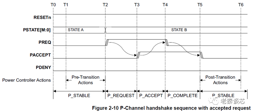
At time T0, the interface is idle, and all handshake signals are low. The interface state is P_STABLE, and the device maintains its current state.
-
At time T1, the controller wants to issue a request and needs to make some preparations in advance. The interface state is still P_STABLE.
-
At time T2, the controller sets PSTATE to the target state B, while changing the PREQ signal to high, and the interface state changes to P_REQUEST. The protocol requires that when the device detects PREQ, PSTATE must be stable.
-
At time T3, the device indicates acceptance of the transition by driving PACCEPT high, while PDENY must remain low (only one of PACCEPT and PDENY can be high during the handshake). The interface state is now P_ACCEPT.
-
At time T4, the controller samples the high PACCEPT and sets PREQ to low, indicating the end of this request. The interface state is P_COMPLETE.
-
At time T5, the device detects PREQ transitioning to low and drives PACCEPT low. Once the controller detects PACCEPT is low, it can perform any required post-transition actions (such as controlling the power switch). The handshake is complete, and the interface state returns to P_STABLE.
-
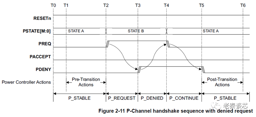
The handshake sequence at times T0, T1, and T2 is the same as in the acceptance request process.
-
At time T3, the device denies the power state transition request issued by the controller, driving the PDENY signal high, while PACCEPT must remain low. The interface state is P_DENIED.
-
At time T4, the controller detects the PDENY signal is high, indicating the device denied the request. The controller drives the PREQ signal low, indicating the end of this request, while restoring the PSTATE signal to its initial state A. The interface state is P_CONTINUE.
-
At time T5, the device detects PREQ transitioning to low and drives the PDENY signal low. Once the controller detects PDENY is low, it can perform any required post-transition actions. The handshake process is complete, and the interface state returns to P_STABLE.
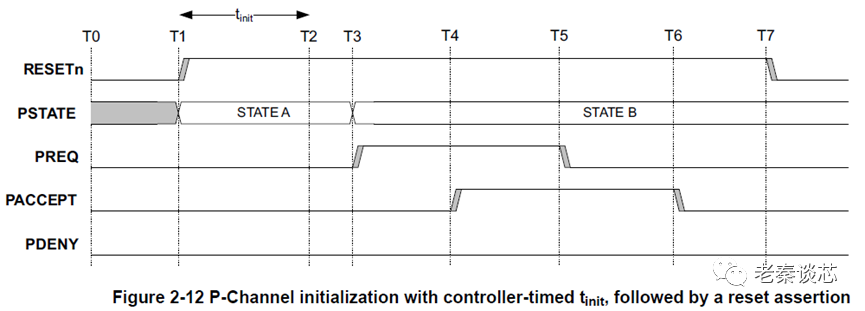
The reset signal for the device can only be set to valid when the P-Channel state is P_STABLE.
Once the device reset is released, the device must enter initialization, at which point the controller sets the PSTATE signal value, and the device samples this signal value to complete the correct initialization process. PSTATE must remain stable after the reset signal is invalid.
The device must provide an initialization time (tinit) to indicate the number of device clock cycles required to ensure capturing the PSTATE value before all possible reset states. PSTATE must remain stable during this time.
The following is the handshake process after the reset, where the controller waits for the tinit time before initiating a request.
The following diagram shows the controller setting PREQ high before the reset is released, and then waiting for the P-Channel transition to complete before issuing further requests.
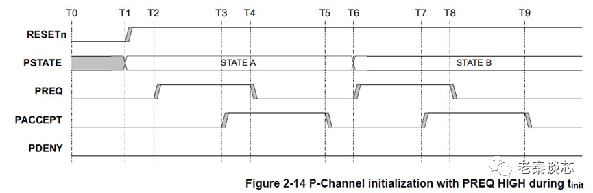
The following diagram shows the controller using the same PSTATE value after the reset is released and setting PREQ high.

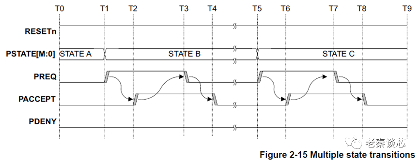
The following diagram shows multi-state transitions, transitioning from state A to state B, and then to state C.
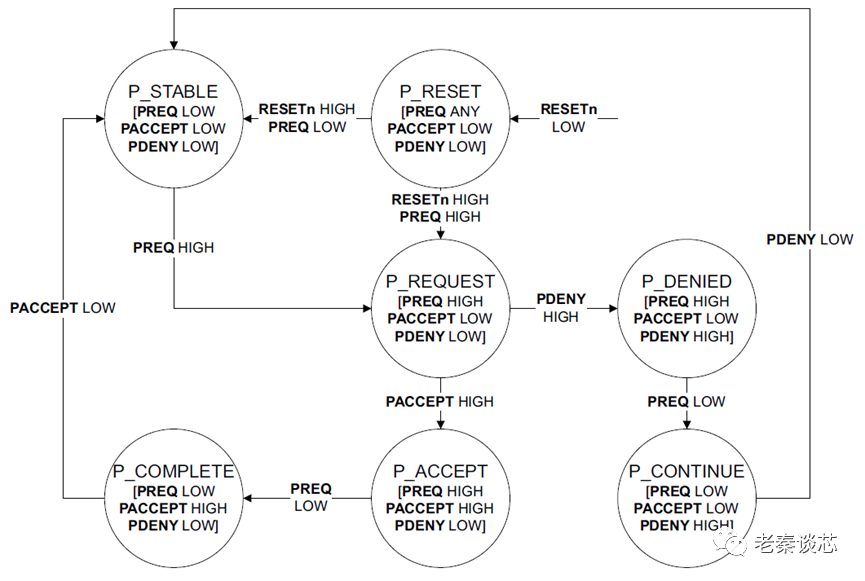
The handshake state and state transition diagram of P-Channel are as follows:
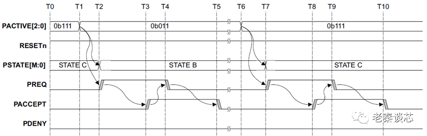
-
PACTIVE[2]: State C
-
PACTIVE[1]: State B
-
PACTIVE[0]: State A
-
All power states supported by the device, including: PSTATE definitions and encodings; allocation of each PACTIVE bit; recommended PACTIVE values for initialization states; unused PACTIVE bits.
-
Power state transitions supported by the device, such as any actions the device takes if the controller initiates a transition request; which device power state transitions can be conditionally denied.
-
PSTATE values for initializing the device after reset release
-
Device initialization time tinit
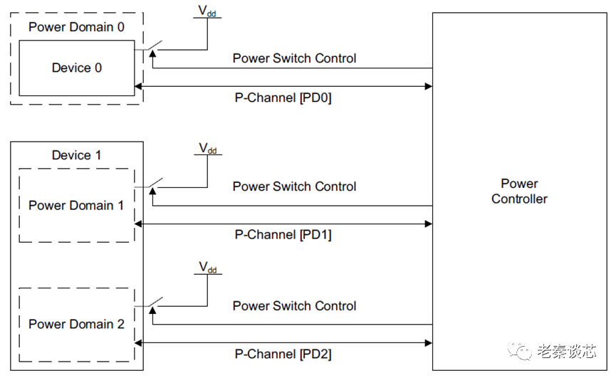
The P-Channel specification provides an example. In this example, there are two devices and three power domains. Device 0 is located in power domain 0, and the power controller uses PD0 to control it. Device 1 is located in power domain 1 and power domain 2, and the power controller uses PD1 and PD2 to control them respectively. In this example, the three power domains are independent.
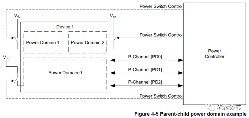
If the power domains are not independent of each other but have a nested relationship, as shown in the following diagram. Device 1 contains three power domains, namely power domain 0, power domain 1, and power domain 2, but domain 0 is the parent domain of domain 1 and domain 2, while domain 1 and domain 2 are child domains, meaning that domain 0 controls domain 1 and domain 2.
Copyright belongs to the original author. If there is any infringement, please contact for deletion.
END


关于安芯教育


安芯教育是聚焦AIoT(人工智能+物联网)的创新教育平台,提供从中小学到高等院校的贯通式AIoT教育解决方案。
安芯教育依托Arm技术,开发了ASC(Arm智能互联)课程及人才培养体系。已广泛应用于高等院校产学研合作及中小学STEM教育,致力于为学校和企业培养适应时代需求的智能互联领域人才。