
Electronic News Sharp Interpretation
Technical Content Updated Daily

I am into DIY projects and will use an FPGA for PC and device data interfaces. I have wanted to create a small development board for a long time, featuring USB high-speed transmission, as well as an external RAM for FIFO as much as possible, with minimal I/O left for the FPGA. I still have stock of Cyclone II, so I continued using EP2C5/EP2C8 for the design, which is a 144-pin QFP packaged FPGA. For the USB interface device, I chose FT232H. I have used their FT232R and FT245R before, but this is my first time using the USB 2.0 high-speed version.
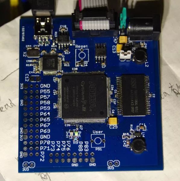
The PCB design is two layers, I would only consider four layers if absolutely necessary (to save costs, as I have not done a four-layer DIY before). If wiring allows, I will include an IS61LV25616 SRAM chip. Power can be sourced from USB 5V or a 5mm DC socket input, with a jumper for selection. To save on USB power costs, I did not use the simple AMS1117 voltage regulator, but arranged two sets of DC-DC converters to provide 5V to 3.3V, and then step down from 3.3V to 1.2V. Designing the board took an entire weekend and several evenings of hobby time, and I still used the old Eagle 4.16 software that I am accustomed to. After another weekend of soldering and debugging, it was completed. Below is the PCB layout:
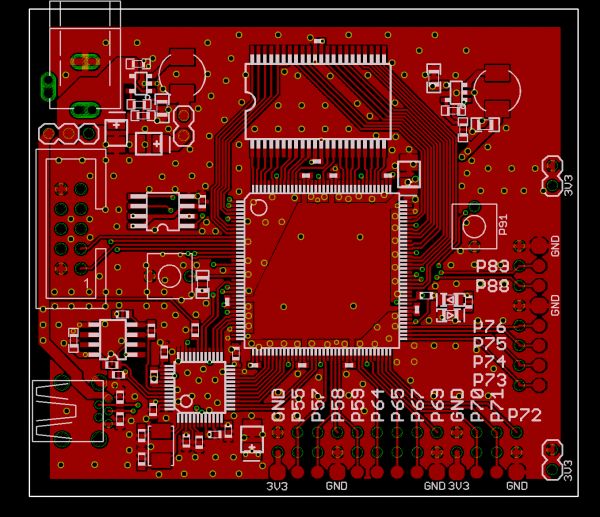
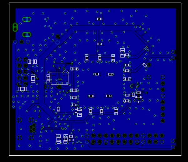
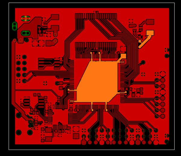
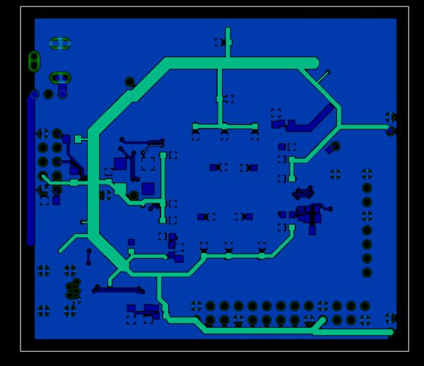
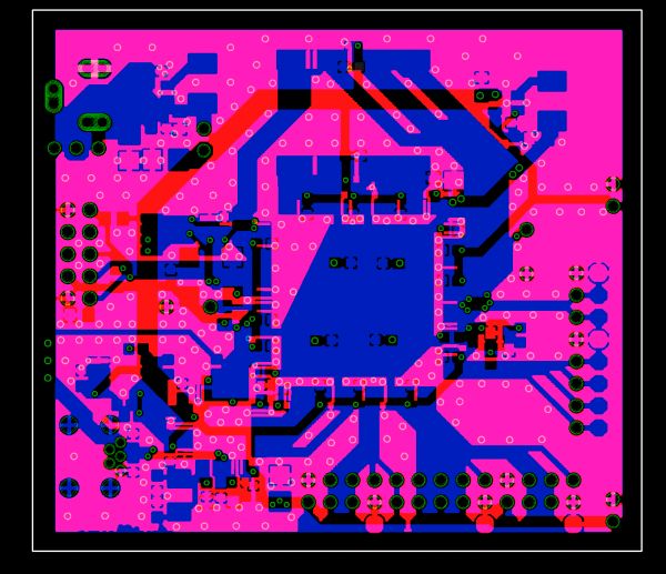
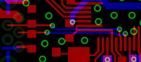
This is my first time doing high-speed USB transmission, and I have no experience. After sending the PCB out, I searched online and found that some say at least a four-layer PCB is required, and some say differential pairs should not go through vias. It seems my routing is not meticulous, which makes me a bit anxious. However, the PCB came back and worked fine, and there were no issues with transmission.
Actual effect picture
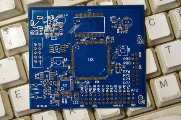
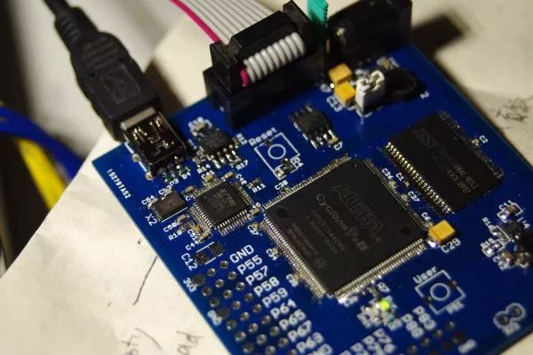
As for the speed of the USB interface, I used synchronous FIFO mode, achieving a transmission rate of over 19MBytes/s from the PC to the board, and over 34MBytes/s from the board to the PC. This is also related to CPU load.
Feel free to clickRead the Original to communicate with the author!
Recommended Reading
Content | WeChat IoT Direct Control of LED Lights
Content | DIY Air Quality Detector
Content | Sharing a Zero-Cross Adjustment Rate Solution
Content | Xiaomi Water Purifier Perfectly Transforms into “Invisible Version”
Content | Smart Appliance Control System with Environmental Detection and Real-Time Monitoring
Content | Understanding Why the RMS Value of Current and Voltage is Effective Value?
Content | Understanding Ceramic Capacitors with Just This One Article
Content | A Clear Explanation of NB-IoT Technology
Content | Teaching You to Run MicroPython on CC3200-LAUNCHXL
Content | When BLE Meets MEMS – Capturing and Tuning