01
What Went Wrong to Study Passive Probes
The problem seems to be solved, but it deepens my questions about passive probes: Why is there such a large resistor in series, and why does the bandwidth of a 1X probe differ so much from that of a 10X probe?
02
Let’s Take Apart a Probe to See What’s Inside
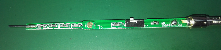
A probe tip, a circuit board, several resistors and capacitors, a single-pole double-throw switch, and a coaxial cable, that’s it.
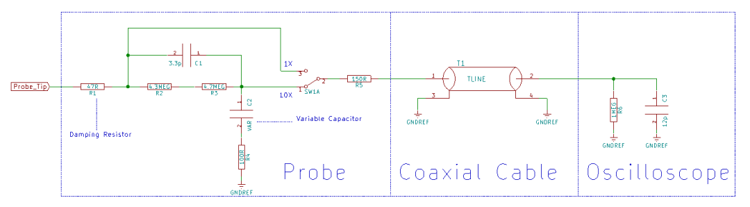
Then the circuit looks like this:
03
Damping Resistor on the Probe
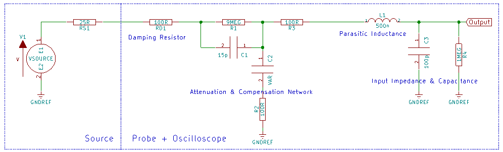
Indeed, there is a significant resistor in series with the probe, but why is such a resistor necessary? Let’s do a simple modeling simulation:
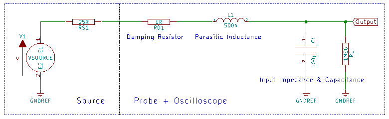
Here, RS1 is the internal source resistance, taken as an empirical value of 25 ohms; RD1 is the input damping resistor of the passive probe, which will be varied during simulation; L1 is the parasitic inductance of the probe cable, taken as an empirical value of 500nH; C1 is the sum of the parasitic capacitance of the probe cable and the input capacitance of the oscilloscope, also taken as an empirical value of 100pF; R1 is the input impedance of the oscilloscope, which is 1M ohm.
By varying the value of RD, we can scan parameters of 1, 25, 50, 75, 100, 150, and 200 ohms, and the system’s frequency response and step response are as follows:
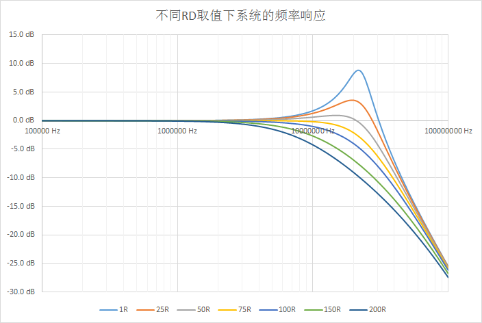
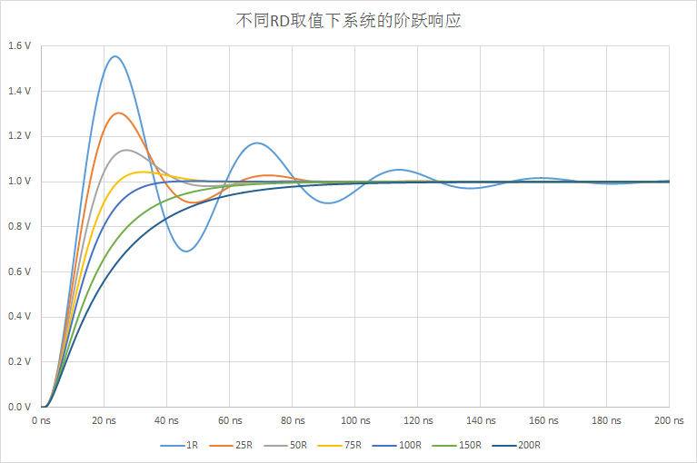
The main function of this damping resistor is to counteract the peaks in the system frequency response caused by the parasitic inductance of the probe. If the damping resistor is too small, the peaks will be large, and the time-domain waveform will exhibit significant overshoot. If the damping resistor is too large, it will lead to insufficient system bandwidth. The actual value is often a compromise obtained through debugging based on the characteristics of the probe and the oscilloscope.
04
Why Does a 10X Probe Have a Higher Bandwidth Than a 1X Probe?
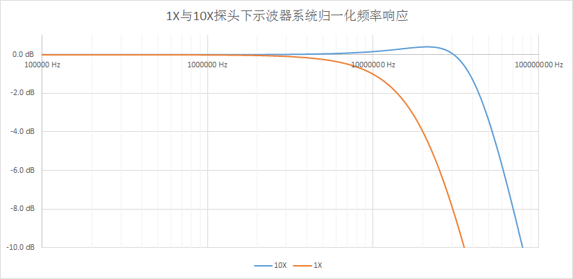
Here, the damping resistor RD1 is set to 100 ohms, and under 1X, the bandwidth is about 17MHz. A compensation and attenuation network is connected in series between the damping resistor and the parasitic inductance of the oscilloscope cable, where C2 is an adjustable capacitor (remember that compensation knob on the probe?). By appropriately adjusting the values of C1, C2, R2, and R3, an ideal system frequency response can be obtained.
05
Not Just Any Coaxial Cable
Having explored the components of the probe, let’s return to the initial question: Can a 1X passive probe be used to match a 50-ohm or 75-ohm system like a coaxial cable? The answer is no, because there is a large damping resistor in series with the probe. Now, if I cut off the probe (probes are not cheap, and it’s painful to do this) and use the remaining coaxial cable to match a 50-ohm or 75-ohm system, can that work? Few people can answer this question correctly.
First, let’s take this piece of coaxial cable to a VNA and see what the results are.
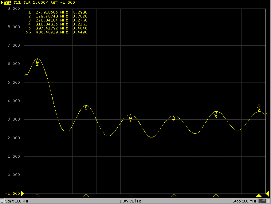
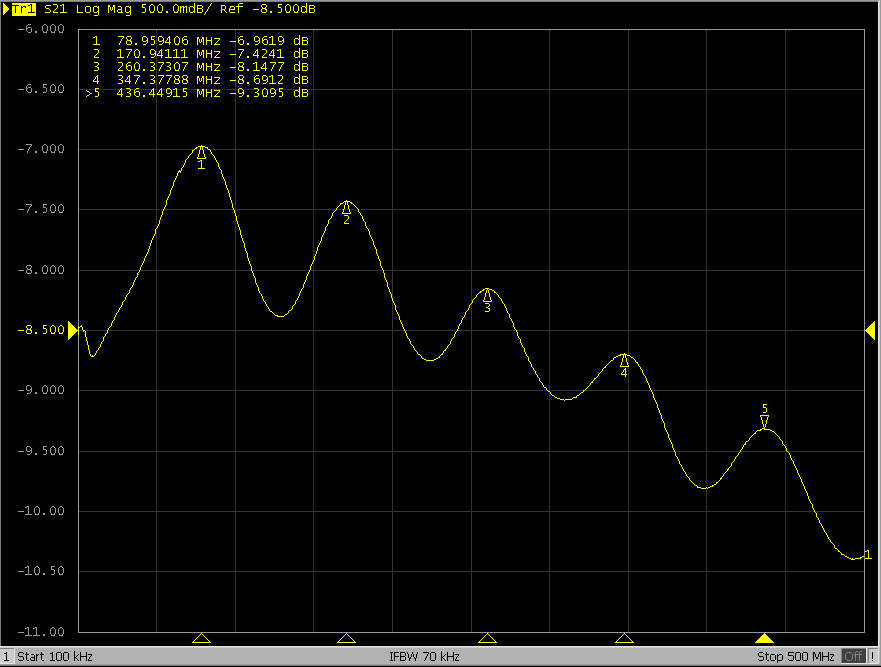
What the heck?! It doesn’t look like a coaxial cable at all. I measured many times, ruled out VNA faults, calibration issues, improper testing methods, and even checked if the coaxial cable was broken… it really looks this ugly.
At this point, careful readers might notice that I initially said the core resistance of the probe measured with a multimeter was over 300 ohms, but in the simplified schematic of the probe later, the damping resistor doesn’t seem to exceed 200 ohms. Did I lose over 100 ohms somewhere in this coaxial cable? Yes, that’s right; the core resistance of this coaxial cable, which is over 1 meter long, measured nearly 180 ohms.
This large resistance is certainly not due to a faulty cable; it must have its reason for existence. Let’s check it with TDR.
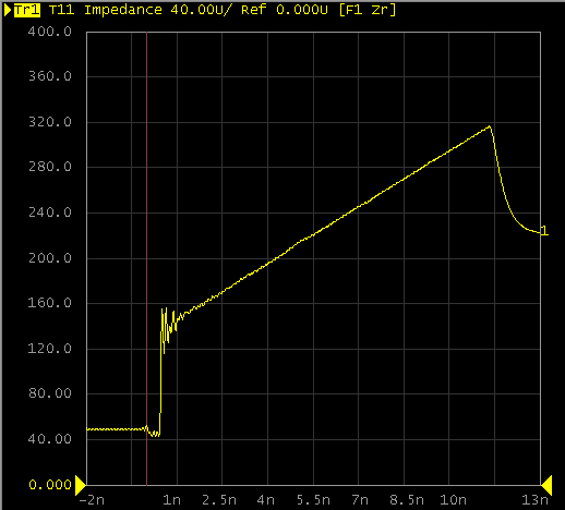
A diagonal line indicates that the impedance is uniformly distributed along the line. Is this the legendary impedance taper line? However, it’s a bit different from a regular impedance taper line because this line has a particularly high insertion loss due to a significant resistive component.
In a system composed of a source, passive probe, and oscilloscope, with an unknown source impedance and a terminal impedance of 1M ohm, how should this transmission line of the probe be matched to this system? Let’s not match it at all; instead, let’s use a high-loss transmission line to reduce reflections, simple and crude. (I’m not too familiar with this RF part, so I don’t know if this statement is correct. If there are any inappropriate parts, I hope readers will point them out.)