Skip to content
High School Knowledge Search Mini Program
1. In modern technology, a sensor refers to a type of component that can sense non-electrical quantities such as force, temperature, light, sound, and chemical components, and convert them into electrical quantities like voltage or current based on certain rules, or convert them into the on/off state of a circuit. After converting non-electrical quantities into electrical quantities, it becomes very convenient for measurement, transmission, processing, and control.
Sensors typically sense non-electrical quantities such as pressure, temperature, displacement, concentration, speed, and pH, while they output electrical quantities such as voltage, current, and charge. These output signals are usually very weak and often need to be amplified before being sent to a control system to produce various control actions. The principle of sensors is shown in the figure below.
3. Classification of Sensors
Common sensors work by utilizing certain physical, chemical, or biological effects. According to the measurement purpose, sensors can be divided into three categories: physical, chemical, and biological.
Physical sensors are made based on the significant changes in certain physical properties (such as resistance, voltage, capacitance, magnetic field, etc.) of the measured substance, such as photoelectric sensors and mechanical sensors.
Chemical sensors are made from sensitive components that can convert the composition and concentration of chemical substances into electrical quantities.
Biological sensors are made using the properties of various biological or biological materials to detect and identify the chemical components within organisms; biological or biological materials mainly refer to various enzymes, microorganisms, antibodies, etc., corresponding to enzyme sensors, microbial sensors, immunosensors, and so on.
Key Point 2: Photoresistor
Photoresistors can convert the optical quantity of light intensity into the electrical quantity of resistance, generally showing a decrease in resistance value with an increase in light intensity.
Key Point Explanation: Photoresistors are made from semiconductor materials. Cadmium sulfide has very few charge carriers (conductive charges) in the absence of light, resulting in poor conductivity. As light intensity increases, the number of charge carriers increases, improving conductivity.
Key Point 3: Thermistor and Metal Thermistor
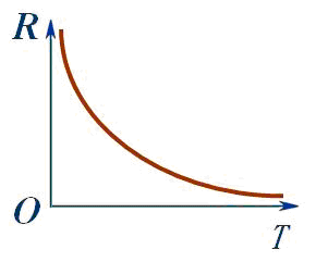
Thermistors are made from semiconductor materials, and their resistance value changes significantly with temperature. The figure shows the resistance-temperature characteristic curve of a certain thermistor.
(1) In the working temperature range, thermistors with positive temperature coefficient (PTC) have resistance values that increase with rising temperature; those with negative temperature coefficient (NTC) have resistance values that decrease with rising temperature.
(2) Thermistors are widely used, primarily in:
① Measuring temperature, controlling temperature, and temperature compensation for components, devices, and circuits using resistance-temperature characteristics.
② Completing voltage stabilization, clipping, switching, and overcurrent protection using non-linear characteristics.
③ Measuring flow, flow rate, liquid level, thermal conductivity, vacuum degree, etc., using the differences in thermal dissipation characteristics in different media.
④ Using thermal inertia as a time delay device.
Some metals have resistance that increases with temperature, and such metals can also be made into temperature sensors, known as metal thermistors.
Both thermistors and metal thermistors can convert the thermal quantity of temperature into the electrical quantity of resistance; however, metal thermistors have better chemical stability and a larger measurement range, while thermistors have higher sensitivity.
Key Point 4: Capacitive Sensors Hall Elements
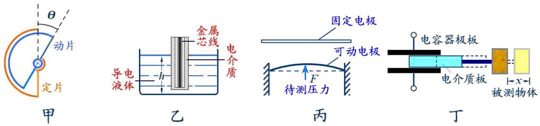
The capacitance of a capacitor is determined by the area of the plates, the distance between the plates, and the dielectric between the plates. If a change in a physical quantity (such as angle, displacement, depth, etc.) can cause a change in one of these factors, resulting in a change in capacitance, then by measuring the capacitance, the change in the physical quantity can be determined. Capacitors used for this purpose are called capacitive sensors.
As shown in Figure A, this capacitive sensor is used to measure angles. When the angle between the movable and fixed plates changes, it causes a change in the area of overlap between the plates, resulting in a change in capacitance. Knowing the change allows us to understand the change in angle.
As shown in Figure B, this capacitive sensor is used to measure liquid level height h. A layer of insulation is applied to the outer wire core, which is placed in a conductive liquid. The wire core and the conductive liquid form two electrodes of the capacitor, and the insulating material on the outer wire core serves as the dielectric. When the height h of the liquid level changes, it causes a change in the area of overlap, resulting in a change in capacitance C. Knowing the change in C allows us to understand the change in h.
As shown in Figure C, this capacitive sensor is used to measure pressure. When the pressure F acts on the movable diaphragm electrode, the diaphragm deforms, causing a change in the distance d between the plates, resulting in a change in capacitance C. Knowing the change in C allows us to understand the change in F.
As shown in Figure D, this capacitive sensor is used to measure displacement x. As the length of the dielectric entering between the plates changes, the capacitance C changes. Knowing the change in C allows us to understand the change in x.
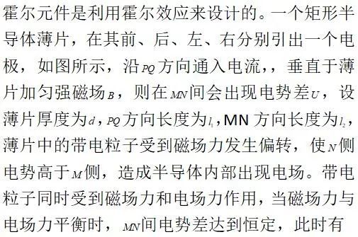
(1). As shown in the figure, a small rectangular conductor (such as indium arsenide) is fabricated with four electrodes E, F, M, N, forming a Hall element.
 which can convert the magnetic induction intensity (a magnetic quantity) into voltage (an electrical quantity).
The Hall element can convert the magnetic induction intensity into an electrical quantity of voltage.
(2). Hall Voltage
which can convert the magnetic induction intensity (a magnetic quantity) into voltage (an electrical quantity).
The Hall element can convert the magnetic induction intensity into an electrical quantity of voltage.
(2). Hall Voltage , where k is the proportionality constant known as the Hall coefficient, which depends on the material of the thin film.
(3). Working Principle of Hall Elements
Key Point 5: Force Sensors
1. Strain Gauge Force Sensor
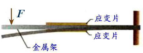
(1) Composition: Comprised of a metal beam and strain gauges.
(2) Working Principle: As shown in the figure, the beam element made of spring steel is fixed at the right end, and a strain gauge is attached to both the upper and lower surfaces of the beam. When a force F is applied to the free end of the beam, it bends; the upper surface stretches while the lower surface compresses, causing the resistance of the strain gauge on the upper surface to increase and the resistance on the lower surface to decrease. The larger the force F, the greater the bending deformation and the change in resistance of the strain gauge. If the current through the strain gauge is kept constant, the voltage across the strain gauge on the upper surface increases while the voltage across the strain gauge on the lower surface decreases. The sensor outputs the difference between these two voltages. The greater the external force, the larger the output voltage difference.
, where k is the proportionality constant known as the Hall coefficient, which depends on the material of the thin film.
(3). Working Principle of Hall Elements
Key Point 5: Force Sensors
1. Strain Gauge Force Sensor
(1) Composition: Comprised of a metal beam and strain gauges.
(2) Working Principle: As shown in the figure, the beam element made of spring steel is fixed at the right end, and a strain gauge is attached to both the upper and lower surfaces of the beam. When a force F is applied to the free end of the beam, it bends; the upper surface stretches while the lower surface compresses, causing the resistance of the strain gauge on the upper surface to increase and the resistance on the lower surface to decrease. The larger the force F, the greater the bending deformation and the change in resistance of the strain gauge. If the current through the strain gauge is kept constant, the voltage across the strain gauge on the upper surface increases while the voltage across the strain gauge on the lower surface decreases. The sensor outputs the difference between these two voltages. The greater the external force, the larger the output voltage difference.