“A 12-bit 104-MS/s SAR ADC in 28nm CMOS for Digitally-Assisted Wireless Transmitters”The calibration method introduced here utilizes low-level capacitors to calibrate high-level capacitors, as the absolute mismatch of high-level capacitors is greater, which in turn has a larger impact on DNL and INL. Calibrating high-level capacitors can effectively improve the dynamic range of the ADC.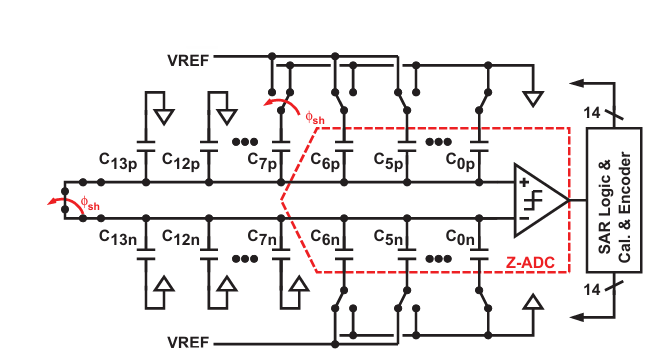 As described in the article, the calibration steps are as follows:
- In the initial phase, all low-level capacitors are connected to VREF, while high-level capacitors, including the ones to be calibrated, are connected to 0, and the two inputs of the comparator are shorted; this is the sampling phase.
- Next, the two inputs are disconnected, and the capacitor to be calibrated is connected to VREF, at this point, the VDAC voltage can be calculated;

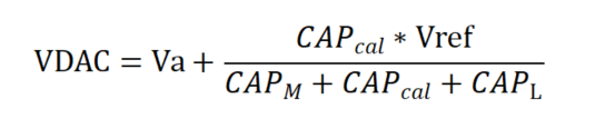
- At this point, the VDACp voltage is as shown above, while the VDACn voltage remains unchanged. We can quantify this voltage using the low-level capacitors, and the resulting low-level value is the true weight of the capacitor CAP_cal.
- Once we have obtained the true weight of the first bit, we proceed to calibrate the other MSBs one by one, storing the calibration values in the digital circuit. After calibration is complete, the digital values obtained during normal sampling are multiplied by these calibration values to yield the true weights. Using the true weights to recover data can maximize the optimization of DNL and INL, thereby improving ENOB.
We set the mismatch of the capacitors to 10%, with a mismatched capacitor array, and began calibration from the eighth bit, assuming that the low-level capacitors have relatively small absolute mismatches. The following results were obtained: The first row shows the nominal capacitor values, i.e., the designed capacitor values;The second row shows the actual capacitor values, which are the values after adding a 10% mismatch;The third row shows the calibrated values.
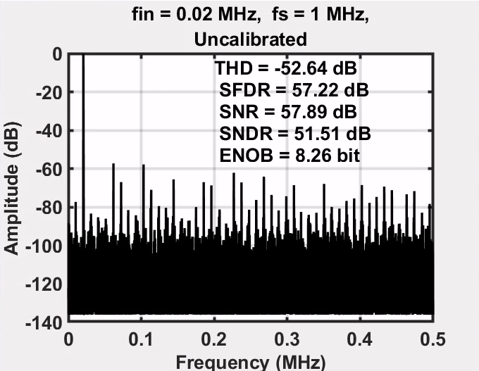
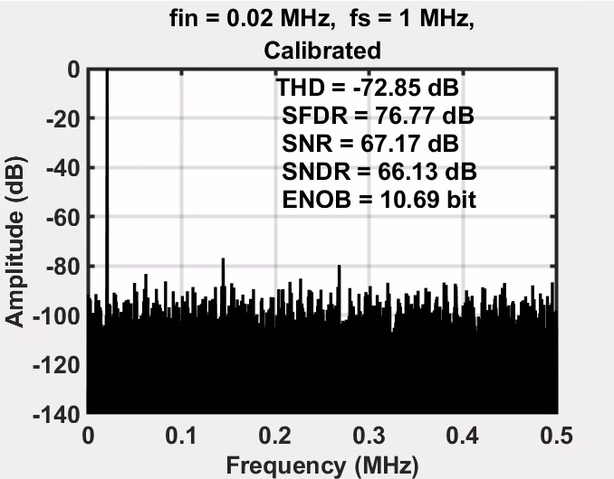
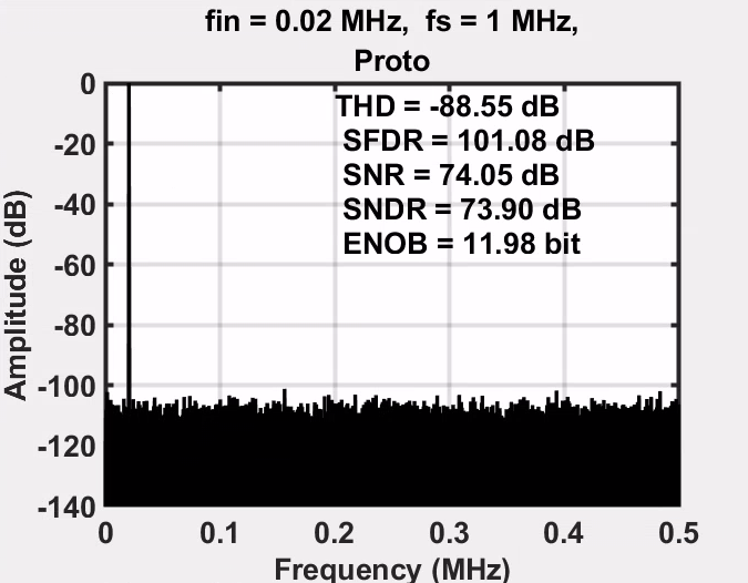 The above images show the output signal spectrum before and after calibration, as well as the signal spectrum under no mismatch conditions. It can be seen that the output signal after calibration shows a significant improvement in ENOB. This calibration scheme is effective. During the experiment, it was found that calibration should not start from too low a bit, as the calibration process is accompanied by the accumulation of calibration errors, which can lead to significant deviations in the calibration of high-level capacitors, making it impossible to improve the signal.