2. How to Configure USB Playback Function
The USB playback function needs to enable “music mode” in the SDK, and the buttons must also be configured accordingly; otherwise, playback content cannot be controlled. Configuring this function requires modifying four files.
(1) board_ac6969d_demo_cfg.h
Path: apps\soundbox\board\br25\board_ac6969d_demo\
Open the file, find “app configuration”, change “TCFG_APP_MUSIC_EN” to 1, and keep “TCFG_APP_BT_EN” as 1:
|
//****************************************************************************// // App Configuration // //****************************************************************************// #define TCFG_APP_BT_EN 1 #define TCFG_APP_MUSIC_EN 1 |
Continue to find “USB configuration”, change “TCFG_UDISK_ENABLE” to “ENABLE_THIS_MODULE”:
|
//*****************************************************************************// // USB Configuration // //*****************************************************************************// #define TCFG_UDISK_ENABLE ENABLE_THIS_MODULE//USB module enable |
The “Trial Sound One” design has three buttons; find “KEY_IO_NUM_MAX” under the key configuration and change the number to 3:
|
#define KEY_IO_NUM_MAX 3 |
Next, find “iokey configuration” and change the value of “TCFG_IOKEY_ENABLE” to “ENABLE_THIS_MODULE”. There are exactly three buttons (POWER, PREV, NEXT) configured here.
Change the “POWER” button to “PLAY”, and also change “TCFG_IOKEY_POWER_xxx” to “TCFG_IOKEY_PLAY_xxx”. Of course, it is not necessary to change it, but it can lead to misunderstandings.
“TCFG_IOKEY_PLAY_ONE_PORT” corresponds to the chip IO port for the play button. Referring to the previously designed schematic, the PLAY button is connected to PB5, so this IO port value should be changed to “IO_PORTB_05”. Other buttons should be modified similarly, resulting in the following code:
|
//****************************************************************************// // IO Key Configuration // //****************************************************************************// #define TCFG_IOKEY_ENABLE ENABLE_THIS_MODULE //Enable IO key #define TCFG_IOKEY_PLAY_CONNECT_WAY ONE_PORT_TO_LOW //One end of the button connects to low level and the other to IO #define TCFG_IOKEY_PLAY_ONE_PORT IO_PORTB_05 //IO key port #define TCFG_IOKEY_PREV_CONNECT_WAY ONE_PORT_TO_LOW //One end of the button connects to low level and the other to IO #define TCFG_IOKEY_PREV_ONE_PORT IO_PORTA_01 #define TCFG_IOKEY_NEXT_CONNECT_WAY ONE_PORT_TO_LOW //One end of the button connects to low level and the other to IO #define TCFG_IOKEY_NEXT_ONE_PORT IO_PORTB_01 |
(2) board_ac6969d_demo.c
Path: apps\soundbox\board\br25\board_ac6969d_demo\
Find “IO KEY” under “#if TCFG_IOKEY_ENABLE”. The VS Code editor automatically detects an undefined error for “TCFG_IOKEY_POWER_CONNECT_WAY” (the original definition no longer exists), marked with a red wavy line, as shown in Figure 2-2-3.
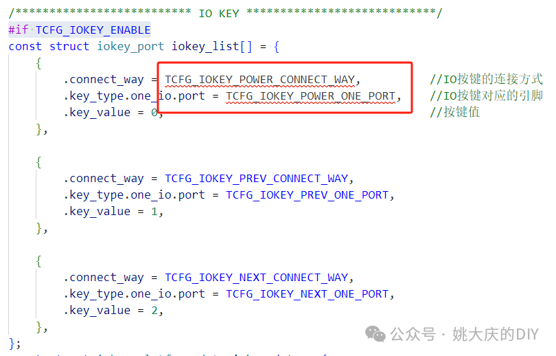
Figure 2-2-3 VS Code detected error
Referring to the “iokey configuration”, change “TCFG_IOKEY_POWER_xxx” to “TCFG_IOKEY_PLAY_xxx”. The specific code is as follows:
|
/************************** IO KEY ****************************/ #if TCFG_IOKEY_ENABLE conststructiokey_portiokey_list[]= { { .connect_way=TCFG_IOKEY_PLAY_CONNECT_WAY, //IO key connection method .key_type.one_io.port=TCFG_IOKEY_PLAY_ONE_PORT, //IO key corresponding pin .key_value=0, //Key value }, { .connect_way=TCFG_IOKEY_PREV_CONNECT_WAY, .key_type.one_io.port=TCFG_IOKEY_PREV_ONE_PORT, .key_value=1, }, { .connect_way=TCFG_IOKEY_NEXT_CONNECT_WAY, .key_type.one_io.port=TCFG_IOKEY_NEXT_ONE_PORT, .key_value=2, }, };
|
(3) iokey_table.c
Path: apps\soundbox\board\br25\board_ac6969d_demo\key_table\
Search for “iokey table for music mode”; here a constant two-dimensional array is defined, which contains 6 elements from [0] to [5], corresponding to 6 keys. Each element is a one-dimensional array containing 6 elements, corresponding to the 6 types of operations: “click, long press, hold, release, double click, triple click”.
For example, the following one-dimensional array indicates that when the key is clicked, playback is started (KEY_MUSIC_PP); when long pressed, the device powers off (KEY_POWEROFF); when held (pressed and held), it remains powered off (KEY_POWEROFF_HOLD); and when released, double-clicked, or triple-clicked, there are no operations (KEY_NULL).
|
//Click //Long Press //Hold //Release //Double Click //Triple Click [0] = {KEY_MUSIC_PP,KEY_POWEROFF,KEY_POWEROFF_HOLD,KEY_NULL,KEY_NULL,KEY_NULL}, |
The “Trial Sound One” circuit design has three buttons, and the previously defined KEY_IO_NUM_MAX is also 3, so we need to modify the length of the music_key_io_table array, commenting out (or deleting) elements [3] to [5], keeping only elements [0], [1], and [2].
Additionally, elements [0], [1], and [2] correspond to the “key_value” settings in the “board_ac6969d_demo.c” file, which are:
“.key_value = 0” corresponds to “PLAY”;
“.key_value = 1” corresponds to “PREV”;
“.key_value = 2” corresponds to “NEXT”.
Therefore, each key’s “click” operation should be changed to “KEY_MUSIC_PP”, “KEY_MUSIC_PREV”, and “KEY_MUSIC_NEXT”, while all other operations such as “long press, hold, release, double click, triple click” should be changed to “KEY_NULL”, as shown below:
|
/*********************************************************** * iokey table for music mode ***********************************************************/ #if TCFG_APP_MUSIC_EN constu16music_key_io_table[KEY_IO_NUM_MAX][KEY_EVENT_MAX] = { //Click //Long Press//Hold//Release//Double Click//Triple Click [0] = { KEY_MUSIC_PP,KEY_NULL,KEY_NULL,KEY_NULL,KEY_NULL,KEY_NULL }, [1] = { KEY_MUSIC_PREV,KEY_NULL,KEY_NULL,KEY_NULL,KEY_NULL,KEY_NULL }, [2] = { KEY_MUSIC_NEXT,KEY_NULL,KEY_NULL,KEY_NULL,KEY_NULL,KEY_NULL }, /* [3] = { KEY_CHANGE_MODE,KEY_NULL,KEY_NULL,KEY_NULL,KEY_NULL,KEY_NULL }, [4] = { KEY_NULL, KEY_NULL,KEY_NULL,KEY_NULL,KEY_NULL,KEY_NULL }, [5] = { KEY_NULL, KEY_NULL, KEY_NULL,KEY_NULL,KEY_NULL,KEY_NULL },*/ }; #endif |
The Bluetooth mode can also use these three buttons, with identical functionality. Find the “bt mode iokey table” and modify it according to the “music mode music_key_io_table” as follows:
|
/*********************************************************** * bt mode iokey table ***********************************************************/ #if TCFG_APP_BT_EN constu16bt_key_io_table[KEY_IO_NUM_MAX][KEY_EVENT_MAX] = { //Click //Long Press//Hold//Release//Double Click//Triple Click [0] = { KEY_MUSIC_PP,KEY_NULL,KEY_NULL,KEY_NULL,KEY_NULL,KEY_NULL }, [1] = { KEY_MUSIC_PREV,KEY_NULL,KEY_NULL,KEY_NULL,KEY_NULL,KEY_NULL }, [2] = { KEY_MUSIC_NEXT,KEY_NULL,KEY_NULL,KEY_NULL,KEY_NULL,KEY_NULL }, /* [3] = { KEY_CHANGE_MODE,KEY_NULL,KEY_NULL,KEY_NULL,KEY_NULL,KEY_NULL }, [4] = { KEY_NULL, KEY_NULL,KEY_NULL,KEY_NULL,KEY_NULL,KEY_NULL }, [5] = { KEY_NULL, KEY_NULL, KEY_NULL,KEY_NULL,KEY_NULL,KEY_NULL },*/ }; #endif |
Finally, there is an “idle mode iokey table”, which is a type of idle mode for the chip. In this mode, the “Trial Sound One” circuit does not design any functions, so all operations are changed to “KEY_NULL”, and elements [3] to [5] are also commented out, as shown below:
|
/*********************************************************** * idle mode iokey table ***********************************************************/ constu16idle_key_io_table[KEY_IO_NUM_MAX][KEY_EVENT_MAX] = { //Click //Long Press//Hold//Release//Double Click//Triple Click [0] = { KEY_NULL,KEY_NULL,KEY_NULL,KEY_NULL,KEY_NULL,KEY_NULL }, [1] = { KEY_NULL,KEY_NULL,KEY_NULL,KEY_NULL,KEY_NULL,KEY_NULL }, [2] = { KEY_NULL,KEY_NULL,KEY_NULL,KEY_NULL,KEY_NULL,KEY_NULL }, /* [3] = { KEY_CHANGE_MODE,KEY_NULL,KEY_NULL,KEY_NULL,KEY_NULL,KEY_NULL }, [4] = { KEY_NULL, KEY_NULL,KEY_NULL,KEY_NULL,KEY_NULL,KEY_NULL }, [5] = { KEY_NULL, KEY_NULL, KEY_NULL,KEY_NULL,KEY_NULL,KEY_NULL },*/ }; #endif |
(4) pwm_led_api.c
Path: apps\soundbox\ui\led\
Refer to the LED lighting mode modification method for Bluetooth mode, find the three “case” items related to music mode, and change their corresponding LED0 to LED1, as follows:
|
caseSTATUS_MUSIC_MODE: log_info(“[STATUS_MUSIC_MODE]”); ui_user_mode_set(STATUS_MUSIC_MODE, PWM_LED1_SLOW_FLASH, 0); break; caseSTATUS_MUSIC_PLAY: log_info(“[STATUS_MUSIC_PLAY]”); ui_user_mode_set(STATUS_MUSIC_PLAY, PWM_LED1_SLOW_FLASH, 0); break; caseSTATUS_MUSIC_PAUSE: log_info(“[STATUS_MUSIC_PAUSE]”); ui_user_mode_set(STATUS_MUSIC_PAUSE, PWM_LED1_ON, 0); break; |
After the above modifications, compilation, and flashing, the “Trial Sound One” circuit will have both Bluetooth and USB playback modes. By default, it enters Bluetooth mode on startup, and when a USB drive is inserted, it automatically switches to music mode and starts playing audio files from the USB drive.
The three buttons correspond to the previous track, next track, and play/pause function keys, and their functionality is the same in both Bluetooth and audio modes.