1. Program Execution Methods
Polling System
Refers to a method where all hardware is initialized first during program execution, followed by a main program that runs in an infinite loop, executing required functions in sequence. The polling system is a simple and reliable method, generally suitable for situations where tasks need to be executed in order without external event influences.
When events requiring external detection, such as button presses, occur during program execution, the real-time response capability of the polling system becomes poor.
int main(void)
{
// Initialize hardware
// Write infinite loop
while(1)
{
// Program 1
// Program 2
…..
}
}
lForeground-Background System
Compared to the polling system, the foreground-background system introduces the concept of interrupts. If an external event occurs, it is handled in the interrupt, while the main program runs in the polling system. The interrupt is referred to as the foreground, while the infinite loop in the main program is referred to as the background. The interrupt will terminate the execution of the background program and jump to the corresponding interrupt service function for processing. After processing, it will continue executing the background program.
If a foreground-background system is used, it greatly improves the program’s real-time response capability, preventing the loss of external events.
int main(void)
{
// Initialize hardware
// Register interrupt, set interrupt trigger conditions
// Execute background program in infinite loop
while(1)
{
// Program 1
// Program 2
…..
}
}
// Interrupt service function
void XXX_IQR(void)
{
// Handle and respond to interrupt
// Return to main program for execution
}
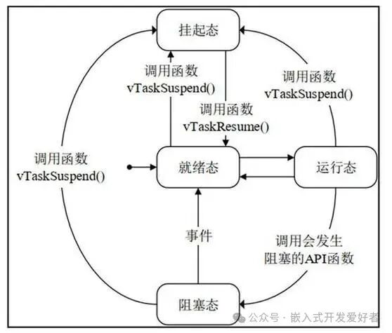
lMultitasking System
Compared to the foreground-background system, the multitasking system also responds to external events in interrupts, but the handling of external events is done within tasks. Tasks have priorities, and higher priority tasks are processed first, thus the program is divided into individual tasks. Each task is an independent infinite loop and cannot return, allowing the operating system to schedule tasks, further enhancing the program’s real-time response capability.
void task1(void) // Task 1
{
while(1)
{
// Execute task 1 functionality
}
}
void task2(void) // Task 2
{
while(1)
{
// Execute task 2 functionality
}
}
int main(void)
{
// Initialize hardware
// Register interrupt, set interrupt trigger conditions
// Task scheduling, managed by the operating system
// Execute background program in infinite loop
while(1)
{
}
}
2. Overview of External Interrupts
1. Concept of Interrupts
An interrupt refers to the CPU handling and responding to external exceptions. An interrupt means to break in, for example, interrupting what is currently being done to handle an urgent matter, and after processing, continuing with the previous task. For instance, playing a game and receiving a call from a girlfriend.
2. Analysis of Interrupt Sources
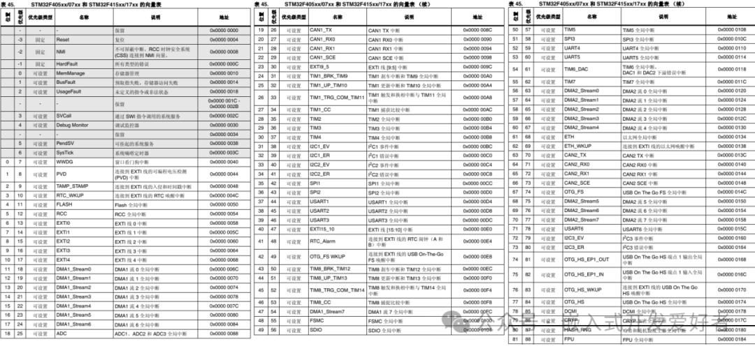
An interrupt source refers to the origin of the interrupt. The interrupt sources are predefined in the kernel, also known as the vector table, which can be referenced in the STM32F4 Chinese reference manual.
The Cortex-M4 core supports a total of 256 interrupts, including 16 core interrupts and 240 external interrupts. However, for the STM32F407 series, only a portion is utilized, including 10 core interrupts (non-maskable interrupts, cannot be controlled by software), and 82 external interrupts (maskable interrupts, can be controlled by software). In total, there are 92.
For STM32 interrupt exceptions, they are divided into two categories:Core Exceptions + External Exceptions, which can be analyzed with the following diagram
 3. Overview of NVIC
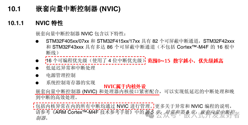
NVIC stands for Nested Vectored Interrupt Controller, which is a peripheral within the core that manages all interrupts, such as enabling or disabling interrupts, and setting interrupt priorities.
Both the Cortex A series and Cortex M series cores have NVIC, which manages core exceptions and external exceptions.
4. Enabling and Disabling Interrupts
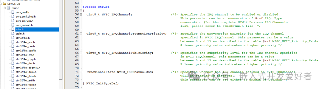
NVIC manages the opening and closing of interrupt channels, and can be understood as the switch for all interrupts. To use interrupts to send interrupt requests, the interrupt channel must be opened in advance. The usage of NVIC is stored in a structure, and this structure and the NVIC function interfaces are defined in misc.c and misc.h.
5. Setting Interrupt Priorities
NVIC uses a 4-bit priority to manage all interrupt channels. The interrupt priorities in STM32 are divided into two types: preemptive priority (main priority) + responsive priority (sub-priority), each having 16 levels (0~15), with lower numbers indicating higher priority.
Significance: If multiple interrupt requests occur simultaneously but cannot be processed at the same time, the interrupt will be handled and responded to based on the priority. For example: My girlfriend asks: If I and your mom fall into the water, who will you save first?
Preemptive Priority (Main Priority): A higher preemptive priority interrupt can interrupt the execution of a lower preemptive priority interrupt.
Responsive Priority (Sub-Priority): In the case of multiple interrupts occurring simultaneously, the one with higher responsive priority is executed first.
Consideration: What is the difference between preemptive priority and responsive priority?????
(1) A higher preemptive priority interrupt can interrupt the execution of a lower preemptive priority interrupt.
(2) Interrupts with the same preemptive priority cannot interrupt each other based on responsive priority.
(3) If interrupts with the same preemptive priority occur simultaneously, the one with higher responsive priority is executed first.
(4) If interrupts with the same preemptive and responsive priority occur simultaneously, they are executed according to the priority in the vector table.
To facilitate user management and response to interrupts, NVIC provides a function interface to group interrupt priorities.
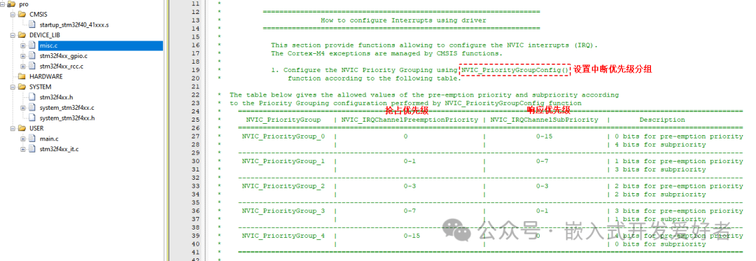
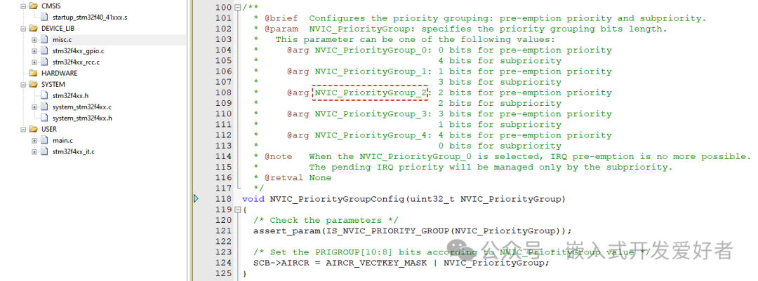
Function Prototype
void NVIC_PriorityGroupConfig(uint32_t NVIC_PriorityGroup)
Function Parameters
Parameter 1: NVIC_PriorityGroup The NVIC priority group to be set, generally NVIC_PriorityGroup_2
Return Value: None
Note: Setting the interrupt priority group should be done at the beginning of the main program and should not be modified arbitrarily, otherwise it may lead to chaotic interrupt management and cause unknown issues in the program.
int main()
{
// Set priority group
NVIC_PriorityGroupConfig(NVIC_PriorityGroup_2);
// Initialize hardware
…….
}
4. Overview of EXTI
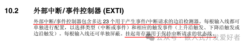 EXTI refers to the External Interrupt/Event Controller, with a total of 23, each having an internal edge detector that can detect rising or falling edges. Each line can generate events or interrupts.
Rising Edge: Refers to the moment when the signal level changes from low to high.
Falling Edge: Refers to the moment when the signal level changes from high to low.
To understand the usage flow of EXTI, one must comprehend the EXTI block diagram.
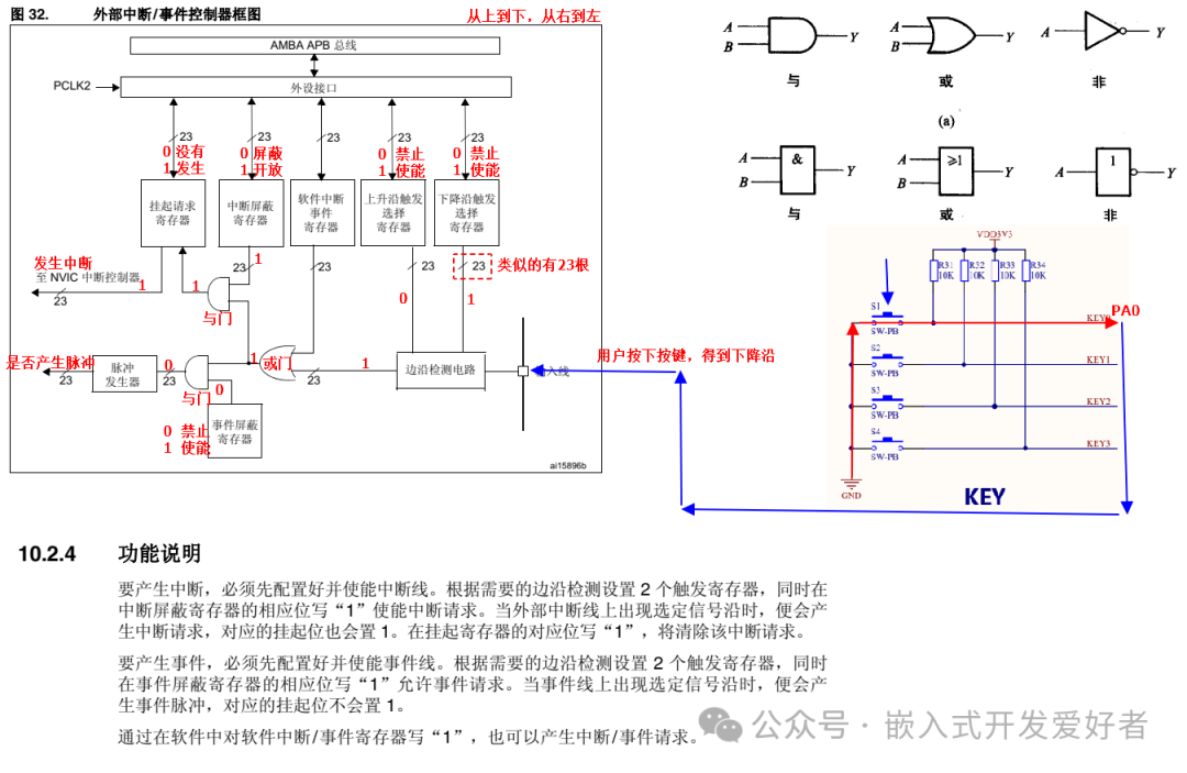
Note: Each GPIO pin can be configured for external interrupts, but there are a total of 16 external interrupt lines related to GPIO, namely EXTI0~EXTI15.
Consideration: The STM32F407 series has 114 GPIO ports, how do they relate to external interrupt lines? Through mapping.
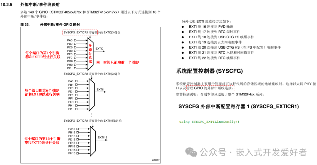
To map external interrupt lines to GPIO ports, a function interface SYSCFG_EXTILineConfig() must be used.
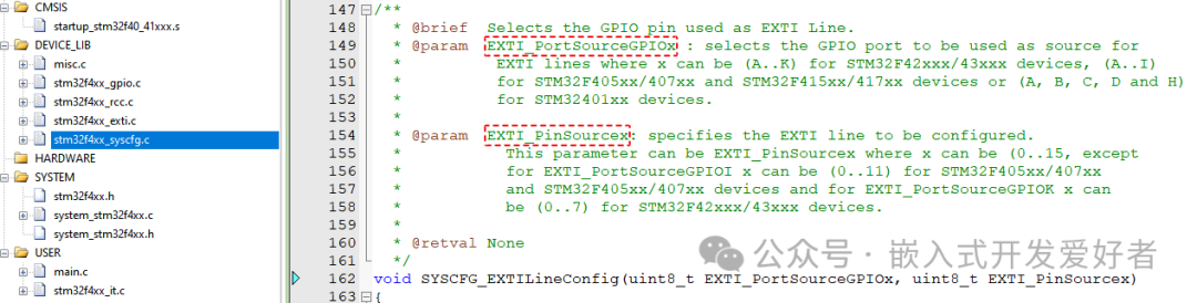
Function Prototype
void SYSCFG_EXTILineConfig(uint8_t EXTI_PortSourceGPIOx, uint8_t EXTI_PinSourcex)
Function Parameters
Parameter 1: EXTI_PortSourceGPIOx The GPIO port to be mapped, such as EXTI_PortSourceGPIOA
Parameter 2: EXTI_PinSourcex The GPIO pin to be mapped, such as EXTI_PinSource0
Note: Since mapping requires the use of the System Configuration Controller (SYSCFG), the clock for the SYSCFG peripheral must be enabled in the code, mounted on the APB2 bus by calling the RCC_APB2PeriphClockCmd() function.
3. Writing Code for External Interrupts
Note: All ports have external interrupt functionality. To use external interrupt lines, the port must be configured as input mode.
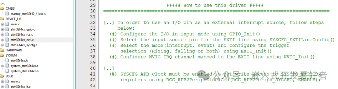
To use EXTI for external event detection, refer to the comments at the beginning of the stm32f4xx_exti.c source file.
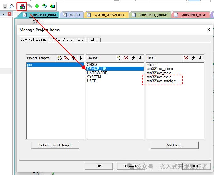
1. The stm32f4xx_exti.c and stm32f4xx_syscfg.c source files should be added to the project. Steps are as follows:
2. Enable the GPIO peripheral clock + SYSCFG peripheral clock, GPIO mounted on the AHB1 bus SYSCFG mounted on the APB2 bus.
3. Define the GPIO initialization structure, configuring the pin mode as input mode + initialize.
4. Call the SYSCFG_EXTILineConfig() function to establish a mapping relationship between the external interrupt line and the GPIO pin.
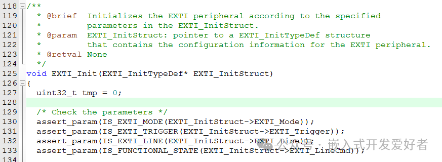
5. Define the EXTI initialization structure, configuring the external interrupt line (mode, trigger method…..) + initialize.
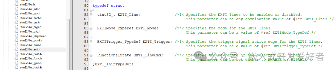
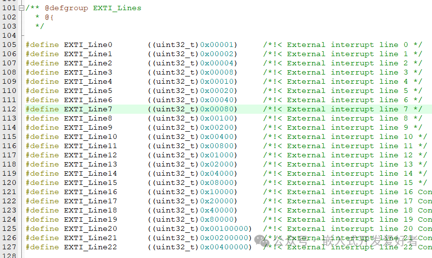
lEXTI_Line The external interrupt line to be used Refer to EXTI_Lines
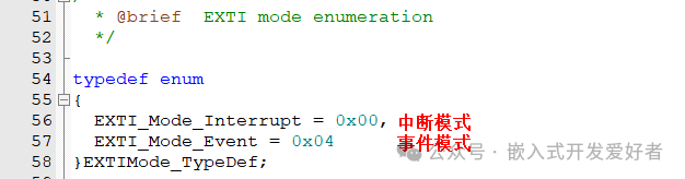
lEXTI_Mode Mode of the external interrupt line (interrupt or event) Refer to EXTIMode_TypeDef
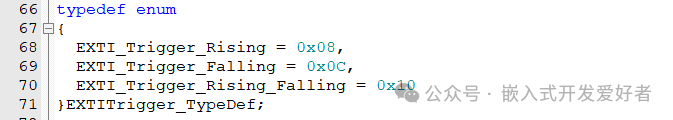
lEXTI_Trigger Edge detection method (rising edge, falling edge, edge) Refer to EXTITrigger_TypeDef
lEXTI_LineCmd Enable external interrupt line ENABLE or DISABLE
Initialize EXTI
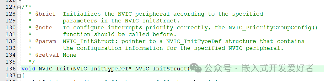
6. Define the NVIC initialization structure and assign values (interrupt channel….) + initialize.
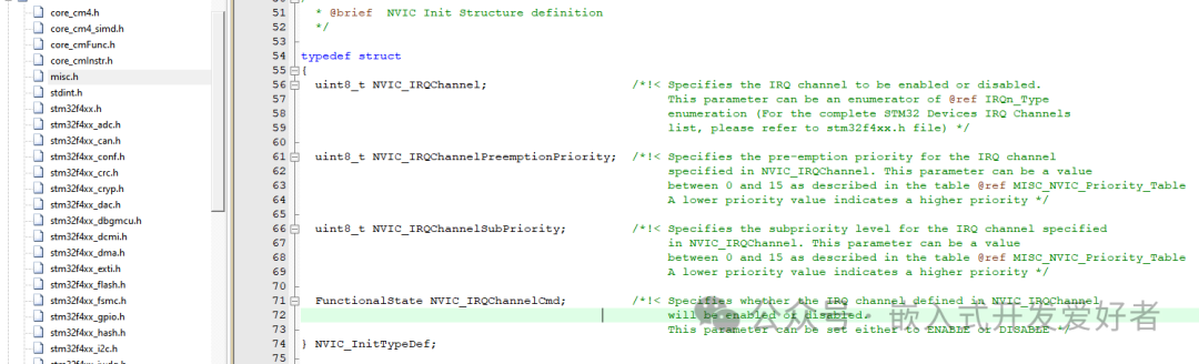
lNVIC_IRQChannel The interrupt channel to be opened Refer to stm32f4xx.h

lNVIC_IRQChannelPreemptionPriority Preemptive priority Must be filled according to the grouping

lNVIC_IRQChannelSubPriority Responsive priority Must be filled according to the grouping
lNVIC_IRQChannelCmd Enable or disable the interrupt channel ENABLE or DISABLE
Initialize NVIC
7. Write the interrupt service function The name of the interrupt service function must be copied from the startup file.
Note: The format of the interrupt service function is fixed (no return value, no parameters). The name is also fixed.
void EXTI0_IRQHandler(void)
{
// Check if the interrupt has occurred if( EXTI_GetITStatus(EXTI_Line0) != RESET )
// Clear the interrupt flag EXTI_ClearITPendingBit(EXTI_Line0)
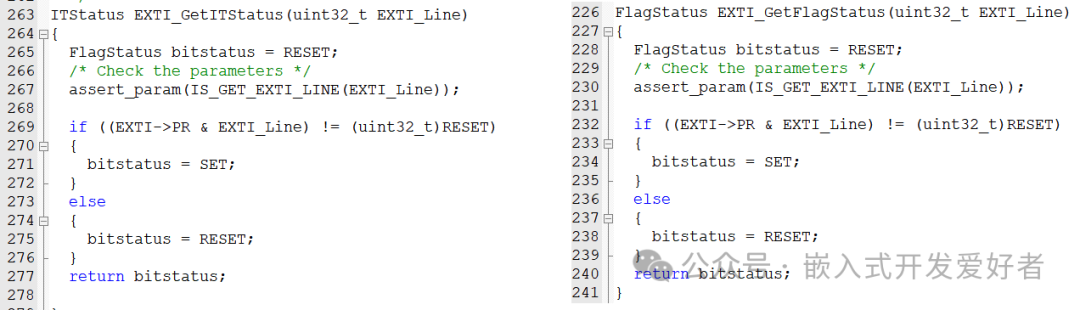
}
Note: The interrupt service function does not need to be called manually, and do not add long delays in the interrupt, as it will reduce the system’s response capability. If complex events need to be handled, a flag can be defined in the interrupt and processed in the main program.