Introduction
In the technical roadmap of a paper, layered diagrams similar to the ones below often appear. Typically, these are drawn using PowerPoint, which can be a cumbersome process. Below, we demonstrate how to create these diagrams in MATLAB with a single command, simply by changing the corresponding file paths.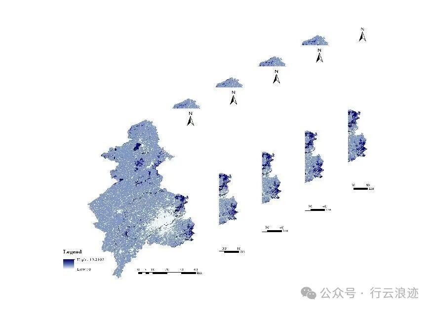
2D Diagram
Change the corresponding file path in the code, as well as the spacing value k for the images. Below are some examples.
clear  clc
fileFolder = fullfile('C:\Users\慢慢\Pictures\图片'); % File path
fileNames = {'1.jpg', '2.jpg', '3.jpg', '4.jpg', '5.jpg'}; % List of image file names to be processed
k = 300; % Movement distance in pixels, can control layer spacing, adjust as needed
% Read the first image
I = imread(fullfile(fileFolder, fileNames{1}));
[m, n] = size(I);
% Initialize the position and size of the first image
x_start = 0;
x_end = m;
y_start = 0;
y_end = n;
figure;
image([x_start, x_end], [y_start, y_end], I);
axis off;
for i = 2:numel(fileNames)
    filename = fullfile(fileFolder, fileNames{i});
    J = imread(filename);
    % Calculate the position of the next image based on the previous image's position and size
x_start = x_start - k;
x_end = x_end - k;
y_start = y_start + k;
y_end = y_end + k;
    % Display the current image
hold on;
image([x_start, x_end], [y_start, y_end], J);
end
axis tight;
axis off;
saveas(gcf, 'C:\Users\慢慢\Pictures\图片\2D.jpg');
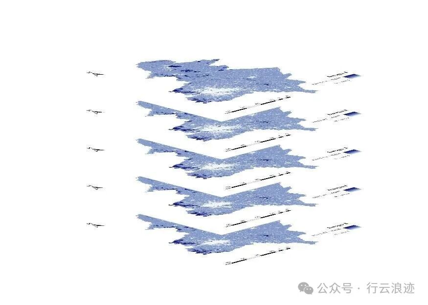
3D Diagram (Horizontal)
This is similar to the 2D operation, but there are many adjustable parameters, such as image spacing, viewing angle, and the 3D rotation tool in the MATLAB popup to adjust the perspective.
clearclc% Set folder path and image file name list
fileFolder = fullfile('C:\Users\慢慢\Pictures\图片');
fileNames = {'1.jpg', '2.jpg', '3.jpg', '4.jpg','5.jpg'};
% Set movement distance
step = 50;
% Create a new 3D coordinate system
figure;
hold on;
% Insert images in a specific order
for i = 1:numel(fileNames)
    % Read the current image
    img = imread(fullfile(fileFolder, fileNames{i}));
    % Resize the image to ensure consistent dimensions
    img = imresize(img, [300, 300]); % Specify uniform size
    % Get the size of the image
    [rows, cols, ~] = size(img);
    % Create a grid
    [X, Y] = meshgrid(1:cols, 1:rows);
    % Calculate Z coordinates to stagger each image on the Z-axis
    Z = ones(size(X)) * (i - 1) * step;
    % Provide valid RGB image data to surf
    C = im2double(img); % Ensure image data is of type double
    % Insert the current image
surf(X, Y, Z, C, 'EdgeColor', 'none', 'FaceColor', 'texturemap');
end  % Set view and axes
view(135, 15); % Set viewing angle
axis tight;
axis equal;
axis off;  % Add title and save image
saveas(gcf, 'C:\Users\慢慢\Pictures\图片\3D.jpg');
3D Diagram (Vertical)
clearclc% Set folder path and image file name list
fileFolder = fullfile('C:\Users\慢慢\Pictures\图片');
fileNames = {'1.jpg', '2.jpg', '3.jpg', '4.jpg','5.jpg'};
% Set movement distance and rotation angle
step = 100;
rot_angle = 180; % Adjust to appropriate angle
% Create a new 3D coordinate system
figure;
hold on;
% Insert images in a specific order
for i = 1:numel(fileNames)
    % Read the current image
    img = imread(fullfile(fileFolder, fileNames{i}));
    % Resize the image to ensure consistent dimensions
    img = imresize(img, [300, 300]); % Specify uniform size
    % Get the size of the image
    [rows, cols, ~] = size(img);
    % Create a grid
    [X, Y] = meshgrid(1:cols, 1:rows);
    % Calculate Z coordinates to stagger each image on the Z-axis
    Z = (i - 1) * step * ones(size(X));
    % Provide valid RGB image data to surf
    C = im2double(img); % Ensure image data is of type double
    % Draw the current image layer and position it at (Z, X, Y), while adding rotation angle
surf(X, Z, Y, C, 'EdgeColor', 'none', 'FaceColor', 'texturemap');
end  % Rotate the entire image (around Y-axis)
h = findobj(gca, 'type', 'surface');
rotate(h, [0, 1, 0], rot_angle, [mean(X(:)), mean(Z(:)), mean(Y(:))]);  % Set view and axes
view(15, 135); % Set viewing angle to XZ plane
axis tight;
axis equal;  %axis off;  % Save image
saveas(gcf, 'C:\Users\慢慢\Pictures\图片.jpg');