Content
Hello everyone, I am Bug Jun~In industrial communication and embedded development, RS485 has become one of the mainstream buses due to its high anti-interference capability and multi-node support. However, many engineers often confuse two key signals when debugging RS485: DE and RTS. They both appear to be “control send” signals, and in some circuits, they are even directly connected.So, are DE and RTS the same thing? Why are they often confused? This article will thoroughly explain the differences and connections between the two from principles to practice.
1
Introduction to DE and RTS
1. DE (Driver Enable) The DE pin controls the transmission enable of the RS485 transceiver, directly controlling the physical layer driver, so it is commonly referred to as the “controller” of RS485.
• DE=Active: The transceiver is in transmit mode, pushing data onto the bus.
• DE=Inactive: The transceiver switches to receive mode, listening to bus data.
In half-duplex communication, it is essential to ensure that only one device occupies the bus at any given time to avoid data conflicts. The usage is that device A raises DE before sending data, and after sending is complete, it immediately releases DE to switch to receive mode. If multiple devices activate DE simultaneously, the bus level becomes chaotic, leading to communication failure, which is a common issue encountered by many beginners when working with RS485.
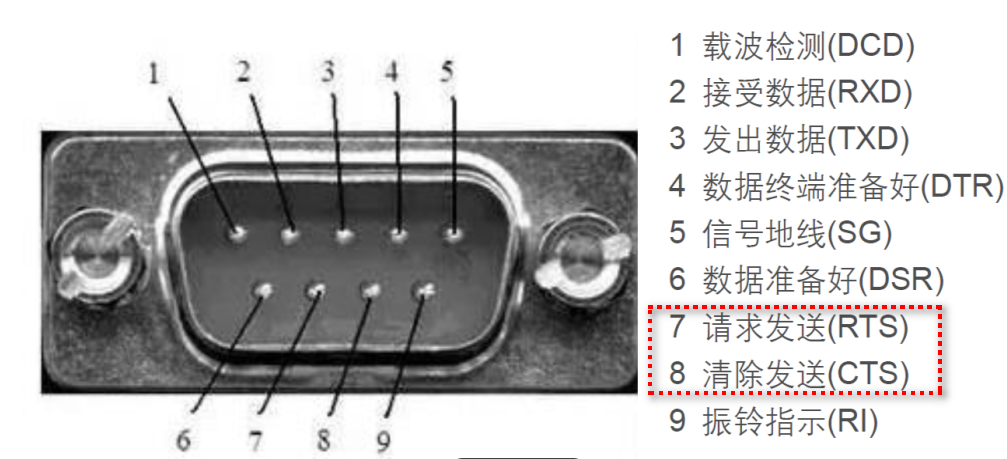
2. RTS (Request To Send)
In fact, RTS was originally unrelated to RS485; it is a hardware flow control signal from RS-232.
It is used to coordinate the transmission rhythm between the sender and receiver, and the general process is as follows:
• RTS=Active: The sender requests the receiver to prepare to receive data.
• The receiver responds: By using the CTS (Clear To Send) signal to notify the sender whether sending is allowed.
Thus, the role of RTS is to prevent buffer overflow at the receiver, ensuring reliable data transmission.
Previously, when working with USB to 9-pin serial port converters for 51 microcontrollers, RTS and CTS were typically included. When sending data from the PC to the device via the serial port, the device would pause the PC’s sending using RTS/CTS flow control to avoid packet loss.
Therefore, the two are designed with completely different intentions!
2
Why the Confusion?
So what exactly causes engineers to have difficulty distinguishing between these two? In some microcontrollers or SoCs with weaker UART interfaces, when designing RS-485 circuits, engineers utilize the automatic control feature of UART for RTS to achieve automatic enabling of DE. This way, software engineers do not need to flip a separate IO pin to simplify RS485 driving, and the logical process is roughly as follows: When sending data, UART automatically pulls RTS low → DE is activated after inversion. When sending is complete, RTS is released → DE is turned off. Moreover, many times RTS and DE are multiplexed into one pin, but they are not the same thing; it is merely a pin multiplexing.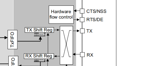 Thus, for UART peripherals like STM32 driving RS485, only DE is needed to control transmission enable, without the need for RTS/CTS flow control.
3
Differences Between the Two
The differences in signal behavior and timing are summarized as follows:
| Feature | DE (Driver Enable) | RTS (Request To Send) |
|---|---|---|
| Activation Timing | Activated in advance before data transmission (Assertion Time), delayed off after sending (Deassertion Time). | Requests the receiver to prepare before sending data (e.g., RTS pulled low), and the receiver responds with CTS. |
| Timing Requirements | Must strictly match the transceiver’s response time to ensure complete data frames. | Timing is defined by the flow control protocol, usually synchronized with data frames, with no additional delay requirements. |
| Signal Polarity | Can be configured to be active high or low (depending on transceiver design). | Typically active low (RS-232 logic: negative voltage is active). |
As you can see, DE requires setting DEAT (Assertion Time) and DEDT (Deassertion Time), such as
• Before sending: DE is activated 2 bit times in advance to ensure the transceiver is stable.
• After sending: DE is delayed 3 bit times to turn off, avoiding truncation of the last stop bit.
Therefore, in UART controllers like STM32, there are controls for DE level polarity and delay. Sometimes, mismatched parameters can lead to unstable RS485 communication.As for the RTS signal:
• Send request: The sender pulls RTS low, and the receiver responds with CTS.
• No strict timing: RTS/CTS only needs to remain coordinated during data transmission, without precise advance or delay.
Creating a stable and reliable embedded system is undoubtedly a continuous accumulation of experience and improvement of knowledge.
Finally
That’s all for today. If you found this helpful, be sure to give a like~
A unique, permanent, and free platform for sharing embedded technology knowledge~
Recommended Albums Click the blue text to jump
☞ MCU Advanced Album 
☞ Embedded C Language Advanced Album
☞ “Bug Says” Album
☞ Album | Comprehensive Programming of Linux Applications
☞ Album | Learn Some Networking Knowledge
☞ Album | Handwritten C Language
☞ Album | Handwritten C++ Language
☞ Album | Experience Sharing
☞ Album | Power Control Technology
☞ Album | From Microcontroller to Linux