This project implements a small yet practical AI demo on the NXP MCX-N947: enabling the MCU to recognize “shoes” or “hats”.
Leveraging the training process of the eIQ Portal along with the acceleration capabilities of the NPU, the entire model construction, quantization, and execution process is very smooth. The project itself is not complex but effectively demonstrates the potential of the MCX-N947 for visual classification at the edge. Below, I will document the complete process for reference and reproduction.
Project Introduction
The NXP FRDM-MCXN947 is a compact and scalable development board featuring external flash memory and an onboard MCU-Link debugger. The following diagram shows the structural block diagram of the N947: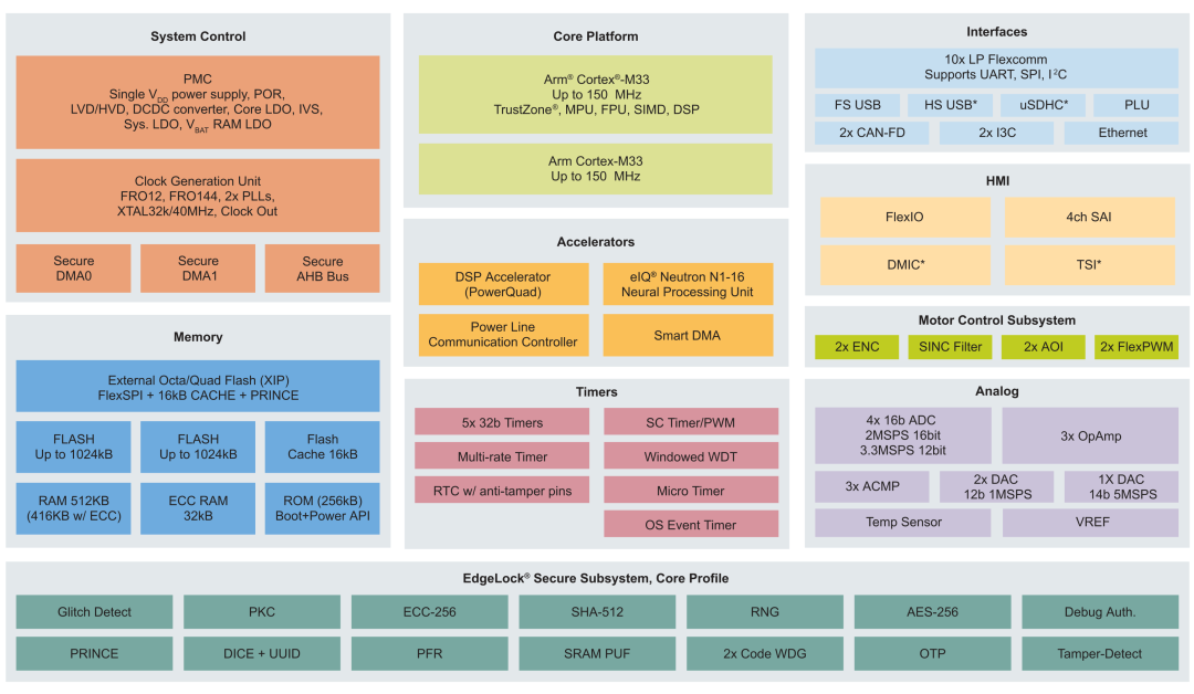
1. Performance of the Development Board
-
MCX-N947 has two Arm™ Cortex™-M33 cores, each with a clock frequency of 150MHz, optimizing performance efficiency, with up to 2MB of dual-block Flash memory, featuring optional full ECC RAM and external flash.
-
Accelerators: Neural Processing Unit, PowerQuad, Smart DMA, etc., ensure the reliability of high-speed neural network computations.
-
Next are the onboard connectors.
-
Ethernet PHY HS USB Type-C SPI/I2C/UART (PMOD/mikroBUS, DNP) WIFI (PMOD/mikroBUS, DNP) CAN-FD.
-
Additionally, it has two onboard sensors: P3T1755 I3C/I2C temperature sensor and touch circuit board.
2. Advanced Peripherals
-
SmartDMA;
-
eIQ®Neutron N1-16 Neural Processing Unit;
-
DSP Accelerator (PowerQUAD, with coprocessor interface);
-
32 Bit Standard General-Purpose Asynchronous Timer/ Counter.
3. Task Overview
Using eIQ NPU to implement machine learning acceleration. You can pair it with a camera module; if you do not have a module, you can use the debugger’s serial port to send images or corresponding audio data directly to the MCU for testing. The requirement is to use eIQ to achieve image classification or audio classification, building a usable NN structure to detect shoes or hats or audio drum sounds or piano detection. I implemented shoe or hat detection. Next, I will guide you step by step to replicate this project.
Setting Up the Development Environment
NXP has a complete development environment that allows you to choose MCUXpresso IDE or MCUXpresso for VS Code. This depends on whether you rely on vscode. In this article, I will introduce this part using MCUXpresso IDE.
MCUXpresso IDE Introduction: MCUXpresso IDE provides developers with an easy-to-use Eclipse-based development environment suitable for NXP MCUs based on Arm®Cortex®-M cores, including general-purpose, crossover, and wireless MCUs. MCUXpresso IDE offers advanced editing, compiling, and debugging capabilities.

MCUXpresso IDE Installation: This part is omitted; please search online.
Building and Running Project Code
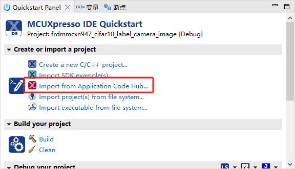
1. Import Example Code Using MCUXpresso IDE
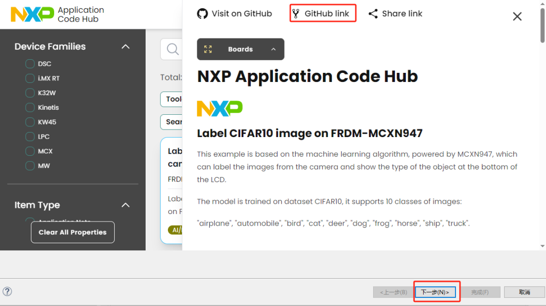
Open MCUXpresso IDE and import Label CIFAR10 image from Application Code Hub.
At this point, our project has been successfully imported. Due to the length of the article, I will not detail the specific code details of this project.
2. Modify the Code According to Our Requirements
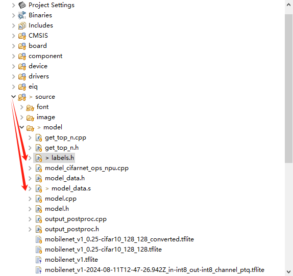
Please note these two files:
source->model->labers.hsource->model->model_data.sIn the labers.h file, we need to modify labers[ ] to the object labels we need to detect, and in model_data.s modify to the name of the model we imported. Note that the imported model should be stored in the model folder. Here is my modified code; please adjust it according to your needs.
static const char* labels[] = {"maozi","xiezi"," "};npu_model_data:.incbin "../source/model/mobilenet_v1.tflite"npu_model_data_end:3. Build and Debug to MCXN947
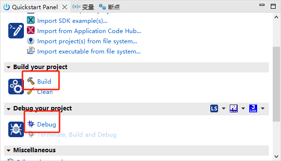
As shown in the figure, this is the build and programming debug process. Before starting the programming, ensure that your MCXN947 is linked to the computer. Please use a data transfer cable to connect your development board. Click the “ Debug“ icon above, or click “ Debug“ in the quick start panel to download the application to the board.
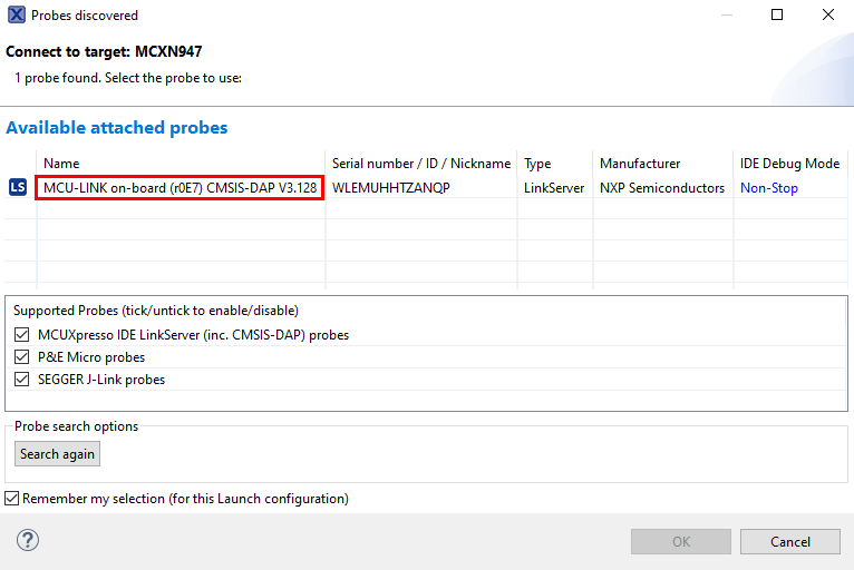
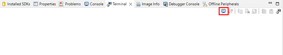
Select MCU-Link CMSIS-DAP hardware debugger and open a serial terminal to view the application output. Select the “Terminal” window, then click the “New Terminal” icon.
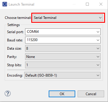
Select “Serial Terminal”, then set the UART to 115200 baud rate, 8 data bits, no parity, and 1 stop bit. Press the OK button.
Building Your Own Model File
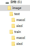
Before this, please ensure you have a suitable and sufficiently large dataset and place it in the root directory as follows:
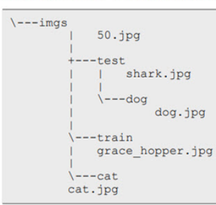
Here is a brief introduction to the NXP neural network development process.
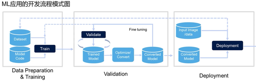
First, we need to have a complete dataset and classification and choose a model for training based on the loss function and whether the image converges to evaluate the model quality, then test the model with the test set to adjust it. The threshold of the Softmax function yields a suitable binary model file (not human-readable) to be burned into the MCXN947 in the form of a C language array int8, after which data is obtained through the native sensor (camera) and analyzed.
1. Install the eIQ Portal Toolchain
This part is omitted; please search online.
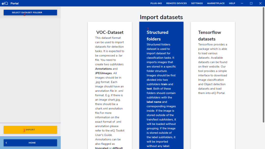
2. Import the Dataset According to Classification into eIQ
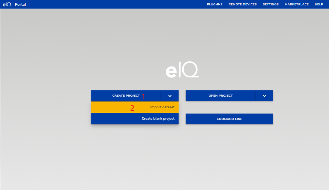
Select create project->import dataset:
3. Import the Dataset as an eiq Project
Structured Folders->SELECT DATASTE FOLDER-> select the dataset we prepared ->IMPORT-> select the project file directory.
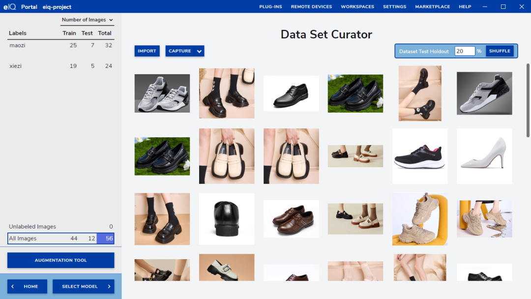
4. Allocate Test Set and Training Set
After successful import, click the upper right corner SHUFFLE to automatically allocate the test set and dataset ratio to 8: 2.
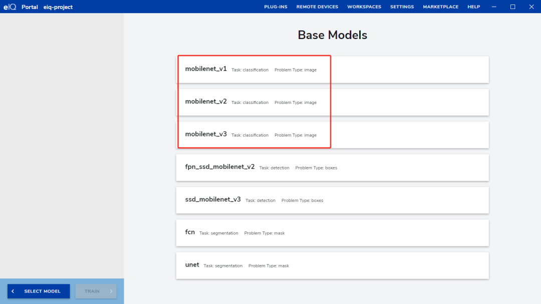
5. Choose the Appropriate Model and Model Input Size
select model->base models->input size ->128,128,3.
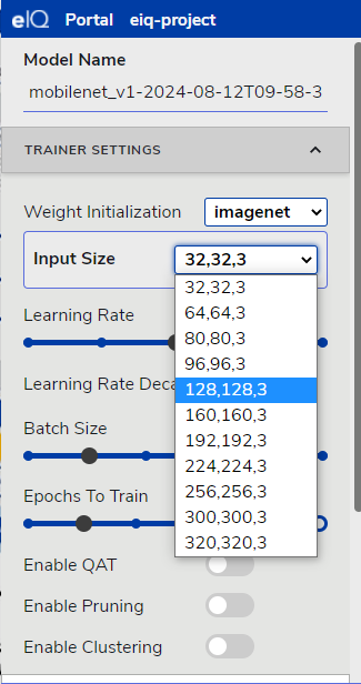
6. Start Training
Epochs To Train->150 times. Note that the number of training times should depend on the model’s convergence level. Click STAR TRAINING to start training.
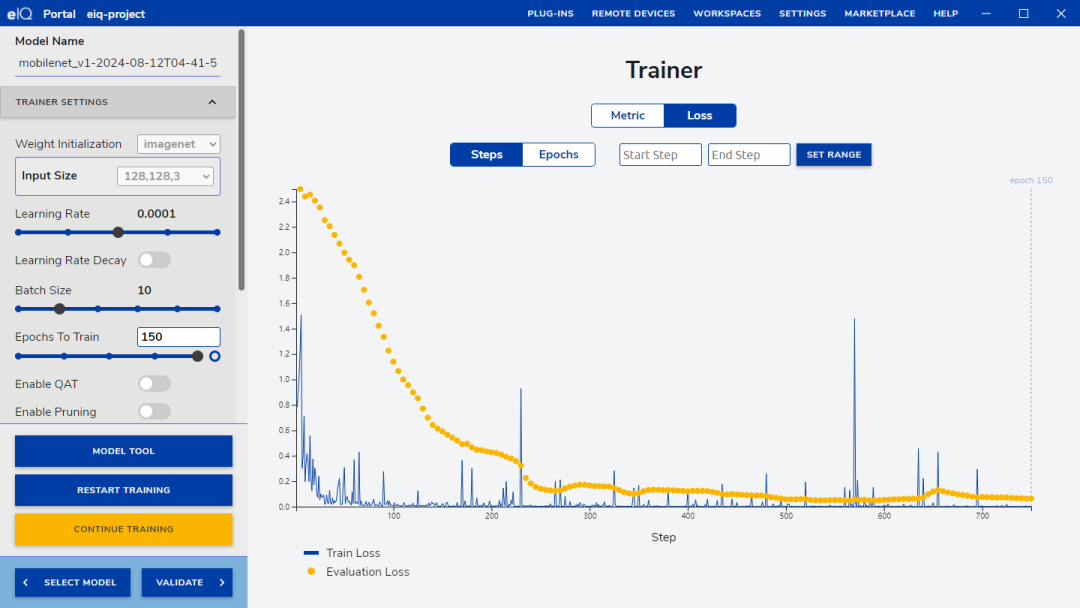
Observe the convergence of the loss function. If the accuracy is consistently unsatisfactory, you can adjust various training parameters and click CONTINUE TRAINING to continue training.
7. Test the Trained Model
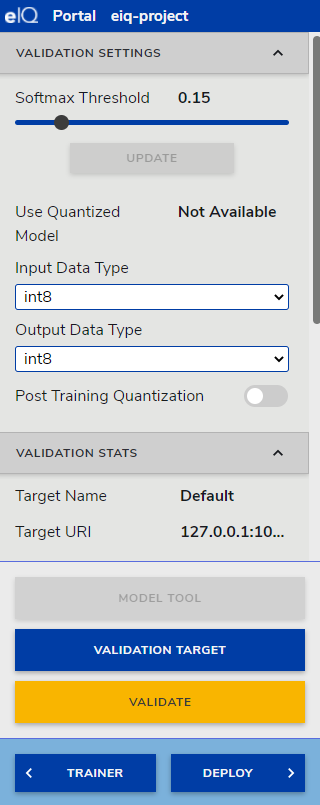
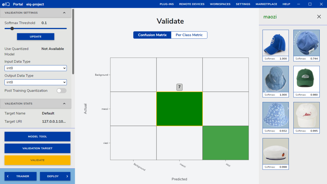
Click VALIDATE to test the training set, setting parameters for Softmax, input DataType and output Data Type. Currently, the MCXN series Neutron NPU only supports int8 type. Here I provide a reference value of 0.15. Click VALIDATE to perform the test and obtain a test sample.
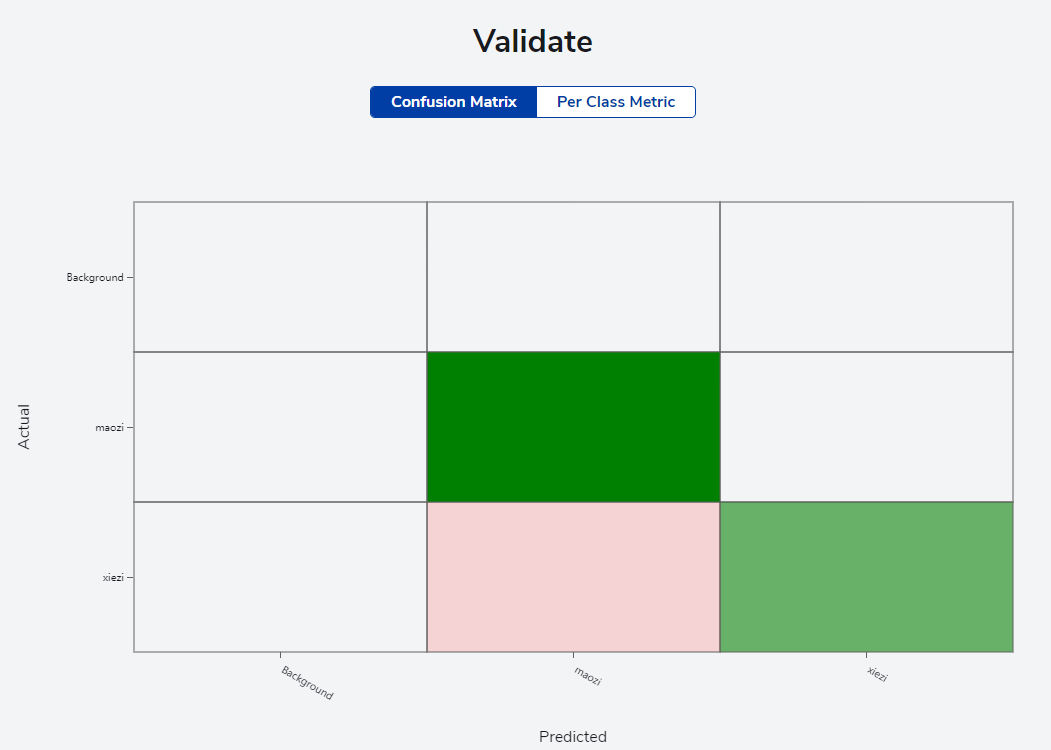
Through the confusion matrix, we can clearly see the classification situation of different categories. In the figure, the x-axis represents the predicted labels, and the y-axis represents the actual labels. We can see the correspondence between each image’s predicted label and actual label: the model I used here was trained for 400 convolution calculations, and the confusion matrix test passed with 100% accuracy.
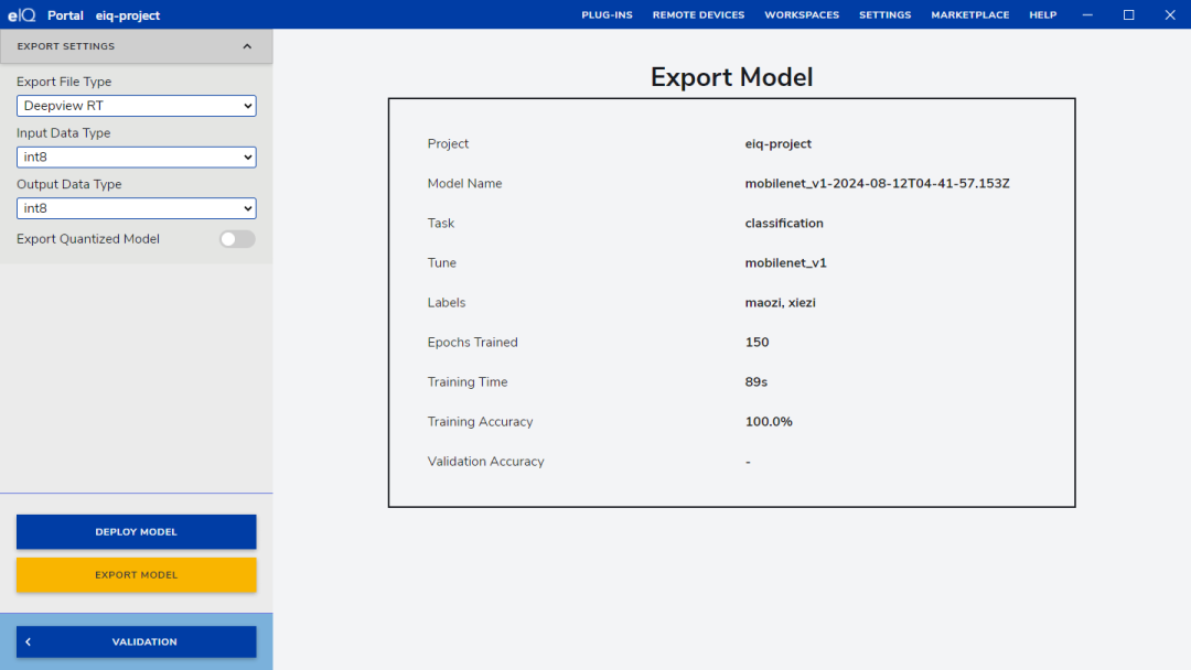
8. Export the Model
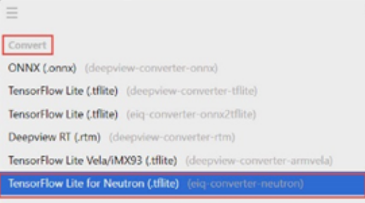
TensorFlow Lite -> DEPLOY -> Export file Type -> input Data Type -> output Data-> TypeExport Quantized Model-> Export Model as shown in the figure below.
Refer to this article for importing the model into the development board: Building and Running Project Code.
Verifying the Project
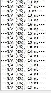
Link the development board to the computer and open the serial port to observe the output N/A, indicating that no objects have been detected; currently, it is background.
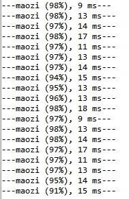
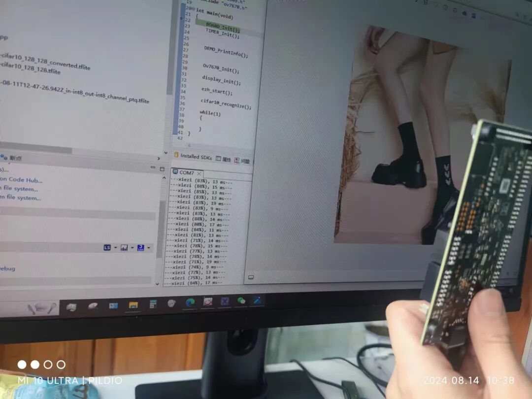
Place an image of a hat, and the serial output is as follows, with the degree of certainty from the neural network in parentheses.
Here, insert a photo with the board + image + output result.
Functionality achieved, task completed.
Code Introduction
First, let’s analyze the code in the main function:
BOARD_Init(); TIMER_Init(); DEMO_PrintInfo(); Ov7670_Init(); display_init(); ezh_start(); cifar10_recognize();These initialization functions set up the project. The most important function here is cifar10_recognize, which is used to run the CIFAR-10 image recognition model. Its main tasks are to initialize the model, prepare input data, run inference operations, and process output results.
if (MODEL_Init() != kStatus_Success) { PRINTF("Failed initializing model"); for (;;) {} }Here, the <span><span>MODEL_Init()</span></span> function is called to initialize the model. If initialization fails, it prints an error message and enters an infinite loop.
size_t usedSize = MODEL_GetArenaUsedBytes(&arenaSize); PRINTF("\r\n%d/%d kB (%0.2f%%) tensor arena used\r\n", usedSize / 1024, arenaSize / 1024, 100.0*usedSize/arenaSize);
 inputData = MODEL_GetInputTensorData(&inputDims, &inputType); outputData = MODEL_GetOutputTensorData(&outputDims, &outputType);
Here, it first retrieves the memory used by the model and prints the relevant information. Then it retrieves the tensor data for the model’s input and output.
 while(1) {     if (g_isImgBufReady == 0)         continue;
     uint8_t *buf = 0;
     memset(inputData,0,inputDims.data[1]*inputDims.data[2]*inputDims.data[3]);
     buf = inputData + (inputData,inputDims.data[1] - MODEL_IN_H) /2 * MODEL_IN_W * MODEL_IN_C;
     memcpy(buf, model_input_buf, MODEL_IN_W*MODEL_IN_H*MODEL_IN_C);
     auto startTime = TIMER_GetTimeInUS();     MODEL_RunInference();     auto endTime = TIMER_GetTimeInUS();
     auto dt = endTime - startTime;     s_infUs = (uint32_t)dt;
     MODEL_ProcessOutput(outputData, &outputDims, outputType, dt);
 }
This part of the code is an infinite loop. First, it checks whether <span><span>g_isImgBufReady</span></span> is 0; if so, it continues to wait. If the image data is ready ( <span><span>g_isImgBufReady</span></span> is not 0), it performs the following operations:
- Zero out
<span><span>inputData</span></span>content. - Based on the offset, copy
<span><span>model_input_buf</span></span>to<span><span>inputData</span></span>. - Record the start time
<span><span>startTime</span></span>. - Call
<span><span>MODEL_RunInference()</span></span>to run the model inference. - Record the end time
<span><span>endTime</span></span>, and calculate the inference time<span><span>dt</span></span>. - Process the inference output data by calling
<span><span>MODEL_ProcessOutput()</span></span>method.
Now let’s look at all the interface functions:
void Rgb565StridedToBgr888(...)Input: Pointer containing RGB565 format data <span><span>pIn</span></span>, source width <span><span>srcW</span></span>, window width and height <span><span>wndW</span></span>, <span><span>wndH</span></span>, starting coordinates <span><span>wndX0</span></span>, <span><span>wndY0</span></span>, pointer to output 888 format data <span><span>p888</span></span>, stride <span><span>stride</span></span>, and a flag indicating whether to subtract 128 <span><span>isSub128</span></span>.Function: Converts RGB565 format image data to BGR888 format and processes the stride. If necessary, subtracts 128 from each output byte (via XOR operation).Internal Implementation:
- Loops through each row of the image window. Reads data from the source image (RGB565) and converts it to BGR888 format based on the formula.
- Subtracts 128 from each group of RGB888 data (24 bits) if needed.
- Copies the converted data to the output buffer
<span><span>p888out</span></span>.
void ezh_copy_slice_to_model_input(...)Input: <span><span>idx</span></span> indicates the index of the current slice,<span><span>cam_slice_buffer</span></span> is a pointer to the camera slice buffer,<span><span>cam_slice_width</span></span> and <span><span>cam_slice_height</span></span> are the width and height of the slice,<span><span>max_idx</span></span> is the maximum slice index.Function: Copies the camera image slice to the model input buffer and converts the image format as needed (RGB565 to BGR888 or RGB888).Internal Implementation:
- Calculates the position of the slice in the overall image.
- Copies a portion of the image data from the camera buffer to the model input buffer as needed.
- Based on the value of
<span><span>MODEL_IN_COLOR_BGR</span></span>, selects to use<span><span>Rgb565StridedToBgr888</span></span>or<span><span>Rgb565StridedToRgb888</span></span>function for format conversion.
The core functionality of this code is image format conversion and data copying. In practical applications, performance can be improved by optimizing memory access and data processing. Additionally, enhancing the readability and maintainability of the code can facilitate subsequent debugging and expansion.
Insights and Reflections
1. Hardware Selection and Architecture Design
First, I selected a suitable camera module, which is the hardware foundation of the entire project. The resolution, frame rate, and compatibility with the MCU of the camera module are all factors that need careful consideration. Ultimately, I decided to use the OV7670 because there is a ready-made driver library in the NXP library, avoiding the need to reinvent the wheel.
2. Image Data Collection and Preprocessing
The quality of image data is crucial for the training and inference performance of machine learning models. During the data collection phase, I ensured the diversity and representativeness of the images to enhance the model’s generalization ability. In the preprocessing phase, I performed cropping, scaling, and normalization of the images to ensure data consistency and quality, which is very helpful for machine learning. For example, I horizontally flipped an image, desaturated it, and increased its saturation, training the model with such a dataset to answer high-quality questions about whether it is an image.
3. Neural Network Structure Construction
Based on existing neural network design guidelines, I chose a lightweight neural network architecture suitable for embedded systems, such as MobileNet. This network performs well on devices with limited computational resources while maintaining a high classification accuracy. I fine-tuned the network structure to better fit the specific classification task of shoes and hats.
4. Deployment on eIQ NPU
The deployment difficulty of this activity is really low, and the learning cost is almost zero, making it very suitable for someone like me who does not have a deep understanding of neural networks to participate in learning. I would like to thank NXP and Hehe Technology for providing me with this learning platform.

Click “Read the original text” to view the project