Hello everyone, I am the owner of a WeChat subscription account that spreads second-hand knowledge about digital chip design. Today, I want to share with you the “Four Essential Tools” for ASIC design: Fold, Expand, Retiming, and Resource Sharing.
Fold & Expand
Fold & Expand, folding and unfolding
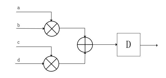
One clock cycle yields a result, using two multipliers, large area, fast speed.
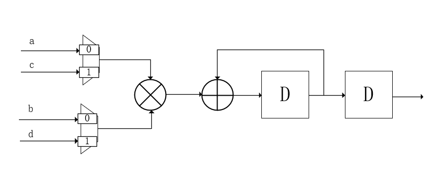
Two clock cycles yield a result, using one multiplier, smaller area, slower speed.
This process is called folding. Unfolding can be seen as the reverse operation of folding. In practical engineering, we appropriately use these two techniques according to requirements to achieve design optimization.
Improving speed and reducing area are two conflicting goals, so in specific designs, a trade-off is necessary. A good design aims to minimize the idle space of logic that occupies a large area, such as multipliers. High reuse is essential.
Retiming
It is common to ask in written tests, what is the Retiming technique?
Retiming is the process of adjusting timing, for example, when encountering complex combinational logic in a circuit with excessive delays, the timing does not meet requirements. At this point, pipelining is employed, inserting registers into the combinational logic to perform operations, trading area for speed.
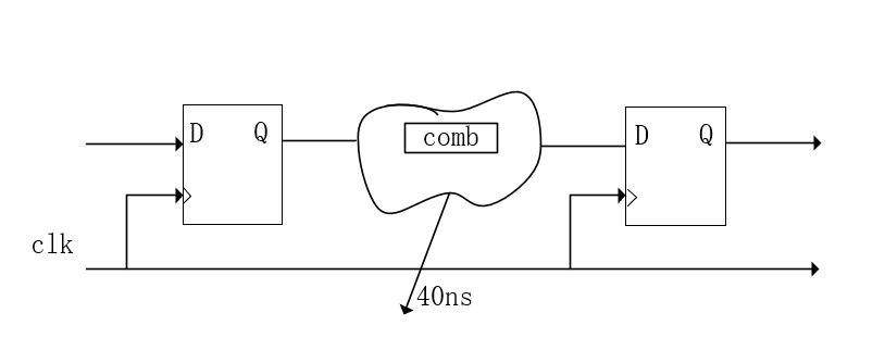
We know that any digital circuit can be equivalently represented as combinational logic plus D flip-flops. The combinational logic path between two D flip-flops determines the system’s operating frequency and the chip’s performance. Therefore, to improve the chip’s operating frequency, registers are inserted into the combinational logic using pipelining.
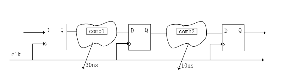
The position of inserting registers must be chosen carefully; the number of registers consumed varies at different positions. For example, if you consume 25 bits of registers at position a and 20 bits at position b, save where you can.
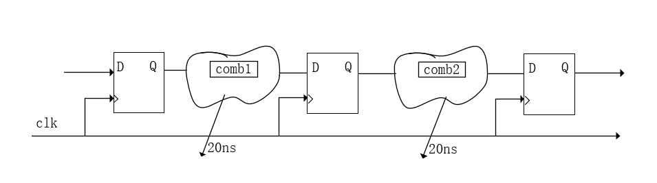
Inserting registers at the front results in a delay of 30ns for comb1 and 10ns for comb2. The system’s maximum operating frequency is determined by the longest path, which means that the maximum operating frequency period of this system cannot be less than 30ns. By inserting a pipeline at the front, we do not change the timing but use retiming techniques to equalize the delays between various combinational logics.
Resource Sharing
From a design perspective, the most common example is the counter; if one counter can achieve the task, do not use two. Try to use the same logic across different lower-level modules to reduce redundant designs.
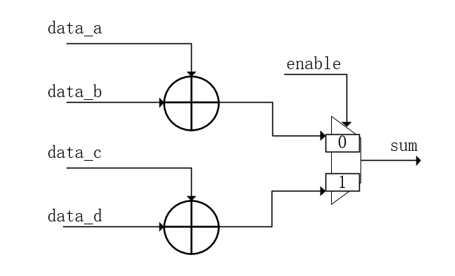
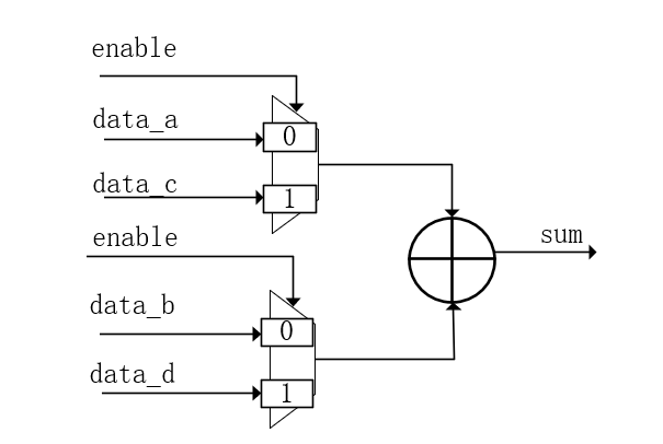
An example of sharing basic logic units is that the area required is: adder > comparator > multiplexer. Commonly referred to as Adder-Comparator-Multiplexer.
A multiplier is essentially a full adder.
Thus, we have the sequence of selecting before comparing, selecting before adding, and selecting before multiplying.
Let’s illustrate this with a diagram.
The most basic level of sharing is based on the sharing of fundamental components. Synthesis tools can perform considerable automatic optimization, and during layout and routing, resource utilization can be further improved. Typically, optimization occurs within the same module, but if your tools are powerful enough, they can break module boundaries for optimization. It is possible to have many modules scattered and mixed together in the layout, and from the backend perspective, module boundaries are not visible. The routing optimization of the tools is difficult to intervene manually.
Conclusion
The above categorization is from the perspective of basic circuit design and data paths. As for control logic, simply put, one phrase: State Machine Method Works Wonders. We will discuss this topic next time.