Microcontroller development engineers and electronics enthusiasts deal with various digital circuits every day. In the process of debugging circuits, in addition to using multimeters and oscilloscopes, logic analyzers are also essential.
A logic analyzer is an instrument that collects and displays digital signals from test devices using a clock, primarily used for timing determination.
Unlike oscilloscopes, logic analyzers do not display continuous analog waveforms but only show two levels (logic 1 and 0).
After setting the reference voltage, the logic analyzer compares the collected signals with the voltage comparator, where signals above the reference voltage are considered logic 1, and those below are logic 0.
This allows the measured signals to be displayed in chronological order as continuous high and low level waveforms, facilitating analysis and debugging for the user.
Using a logic analyzer, users can easily set signal trigger conditions to start sampling, analyze the timing of multiple signals, capture signal interference spikes, and decode level sequences according to rules to complete communication protocol analysis.
Logic analyzers are mainly divided into two categories based on their hardware functionality and complexity: standalone (single unit) logic analyzers and PC-based virtual logic analyzers.
Standalone logic analyzers integrate all software and hardware into one instrument, making them easy to use. Virtual logic analyzers require a computer to utilize its powerful computing and display capabilities for data processing and display.
Professional logic analyzers typically have numerous sampling channels, ultra-fast sampling speeds, and large storage depths, but their expensive prices are often unaffordable for individuals.
As essential tools for engineers, many entry-level logic analyzer designs are available today. Although their overall functionality may not compare to high-end professional instruments, achieving specific functions at a lower cost is also a very successful design.
The logic analyzers discussed in this article mainly refer to such entry-level designs.
PC-based logic analyzers were once mainstream, but in recent years, computer systems have gradually stopped being equipped with parallel ports, making such designs outdated and only valuable for principle learning.
Another type of logic analyzer is based on low-speed microcontrollers. Many enthusiasts have designed their projects using common microcontrollers like PIC and AVR. However, these microcontroller-based logic analyzers share a common weakness: their sampling speeds are usually not more than 1MHz.
Entry-level logic analyzers based on USB IO chips are currently the most popular.
For example, Saleae Logic and similar products like USBee. These products mainly use a USB IO chip, such as Cypress’s CY7C68013A-56PVXC, where all signal triggering and processing work is done by software on the computer, and the hardware part is merely a data logger.
The maximum sampling speed is 24MHz. They can sample an “unlimited number” of times since all data is stored on the computer.
Currently, most have up to 8 channels, and increasing the number of channels proportionally reduces the maximum sampling speed. These products are simple, easy to use, and inexpensive, making them great tools for debugging microcontroller development work.
The main drawback is that with a sampling speed of only 24MHz and 8 channels, they cannot handle high-speed parallel buses.
Further designs require adding FPGA, SRAM, and other components to address speed and channel quantity issues.
Next, we will take the Saleae logic analyzer as an example to briefly introduce its features and usage methods by sampling and analyzing I2C bus waveforms and PWM waveforms.
First, let’s introduce the process of using a logic analyzer to sample the data writing process of the microcontroller to the I2C device AT24C16.
Hardware Connection
1. First, connect the GND of the logic analyzer to the GND of the target board to establish a common ground.
2. Select the signals to be sampled, which are the SDA and SCL of the AT24C16, connecting SDA to channel 1 (Input 1) of the logic analyzer and SCL to channel 2 (Input 2).
3. Connect the logic analyzer to the computer’s USB port, and Windows will recognize the device, displaying the USB device identifier in the lower right corner of the screen.
Software Usage
1. Run the Saleae software. At this point, the hardware of the logic analyzer is connected to the computer, and the software will display [Connected].
2. Set the sampling quantity and speed. I2C is low-speed communication, so the speed does not need to be too high; here, it is set to 20M Samples @ 4M Hz, which allows continuous sampling for 5 seconds.
3. Set the protocol by clicking the “Options” button in the upper right corner, finding analyzer1, and setting it to the I2C protocol, as shown in Figure 1.
4. Click the “Start” button to begin sampling.
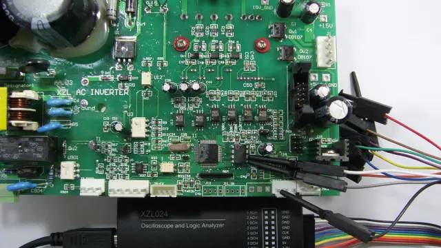
Figure 1
Data Analysis
After sampling ends, the waveform can be observed, as shown in Figure 2. Since we set it to I2C analysis, it not only shows the waveform but also displays the byte content decoded according to the I2C protocol.
The microcontroller writes to the AT24C16 at address 0x00, writing numbers like 10000. The waveform starts with a “start” signal, followed by the AT24C16 identifier 0xA2, the write address 0x00, and data 0x10, 0x27, etc. Since writing is done byte by byte, 0x2710 = 10000, indicating successful sampling.
Hover the mouse over the waveform and click the left mouse button to zoom in. The result is shown in Figure 3, where after the “start” condition, the SCL has 8 continuous high-level pulses, and the corresponding SDA signal is 10100010, which is 0xA2. The high level of the 9th pulse is 0, which is the ACK flag.
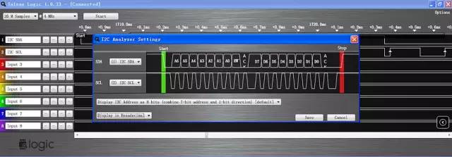
Figure 2
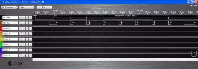
Figure 3
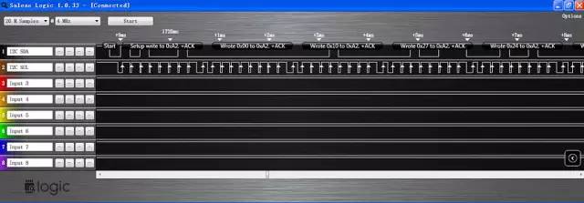
Figure 4
The above briefly introduced the process of using a logic analyzer for I2C analysis, demonstrating that the operation is quite simple.
Next, we will introduce using a logic analyzer to sample the 6 PWM waveforms of a three-phase AC motor driver.
Hardware Connection
1. First, connect the GND of the logic analyzer to the GND of the target board to establish a common ground, as shown in Figure 5.
2. Select the signals to be sampled, which are the output pins of the 6 PWM waveforms from the microcontroller, connecting them to channels 1 (Input 1) through 6 (Input 6) of the logic analyzer, and rename the channels to Utop, Ubottom, Vtop, Vbottom, Wtop, WBottom, representing the upper and lower arms of the three outputs.
3. Connect the logic analyzer to the computer’s USB port, and Windows will recognize the device, displaying the USB device identifier in the lower right corner of the screen.
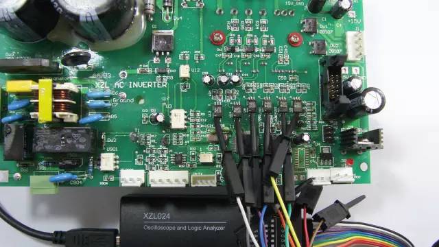
Figure 5
Software Usage
1. Run the Saleae software. At this point, the hardware of the logic analyzer is connected to the computer, and the software will display [Connected].
2. Set the sampling quantity and speed. The frequency of the PWM is 15kHz, so it is set to 2M Samples @ 4MHz.
3. Set the trigger condition, which can be left as default “—-“.
4. Click the “start” button to begin sampling.
Data Analysis
After sampling ends, the waveform can be observed, as shown in Figure 6.
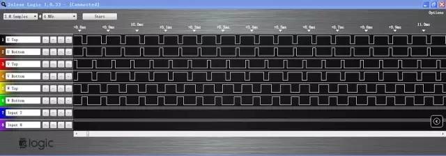
Figure 6
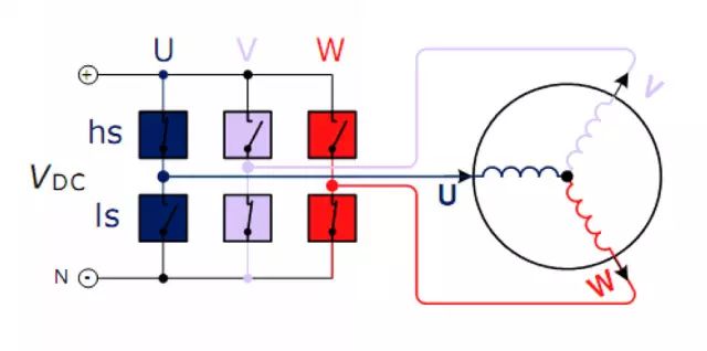
The typical PWM for a three-phase motor driver is complementary, meaning the states of the upper and lower waveforms in a signal group are opposite, controlling the states of the upper and lower switches of the bridge arm to avoid short circuits caused by simultaneous conduction, as shown in Figure 7.
Hover the mouse over the waveform and continuously click the left mouse button to zoom in. See Figure 8.
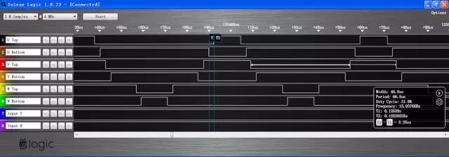
Figure 8
Place markers on the falling edge of UBottom and the rising edge of UTop. In the display box at the bottom right, it shows T2-T1=2.25μs, which is the time difference between turning off and turning on, professionally known as “dead time”.
Additionally, the PWM width is 45.5μs, the period is 66.6μs, the duty cycle is 31.6%, and the frequency is 15.0376kHz, among other information. This represents a typical SVPWM waveform of a three-phase motor inverter.
The above two examples briefly introduced the usage of logic analyzers, hoping to provide help and inspiration to developers.