Concept of Event-Driven
There are many examples of event-driven in life, like sneaking a nap during self-study while the teacher is not watching.
We all went through high school, which was tough. High school students feel that sleeping is the most luxurious thing in the world; sometimes, you can even fall asleep while standing! The teachers are strict, and sleeping in class is not allowed, or else you would be criticized!
In contrast, evening self-study sessions are relatively relaxed. The teacher only comes to patrol occasionally, so there is a chance to sneak in a short nap.
The question now is, how can one sleep well without being discovered by the teacher? Evening self-study is relatively relaxed, and the teacher only comes to patrol occasionally. The question is, how can one sleep well without being discovered?
We currently have three sleeping plans:
-
Plan A: Just fall asleep without caring about anything; just sleep enough and forget about it. Sometimes, the teacher might not come all night.
-
Plan B: Sleep intermittently, set an alarm to ring every 5 minutes, wake up to check if the teacher is coming, and if not, reset the alarm and go back to sleep.
-
Plan C: Have a desk mate keep watch while you sleep, and you don’t have to worry about anything. When the teacher comes, let your desk mate poke you awake.
No matter which plan you choose, I used Plan C back in high school; it was safe and comfortable.
Plan C has unique characteristics: sneaking a nap during self-study is your own business, whether or not the teacher catches you is also your own affair; these have nothing to do with your desk mate. However, the role of the desk mate is crucial for Plan C, as they are responsible for monitoring the teacher’s patrol and waking up the sleeper, making them an essential component of the event-driven mechanism.
In an event-driven mechanism, the object is always in a “sleeping” state concerning external events, while the detection and monitoring of external events are entrusted to a third-party component.
Once the third party detects an external event, it will activate a certain mechanism to wake the object from its “sleeping” state and inform the object of the event. Upon receiving the notification, the object will take a series of actions to respond to the event and then return to the “sleeping” state, repeating this cycle.
Have you noticed that the event-driven mechanism is quite similar to the interrupt principle of microcontrollers?
Event-Driven and Microcontroller Programming
Now let’s return to the microcontroller system and see how the event-driven concept applies to microcontroller programming. When I was still a novice in microcontrollers (of course, I still haven’t become an expert), the experts online advised me that a good microcontroller program should be layered. For a long time, I had no understanding of the concept of layering.
-
What is program layering?
-
Why should programs be layered?
-
How should programs be layered?
As the amount of code I had increased and the functions I implemented became more numerous, the concept of software layering gradually became clearer in my mind, and I grew to admire the foresight of the experts.
Microcontroller software indeed needs to be layered, at least into two layers: the driver layer and the application layer. The application is the core of the microcontroller system, and the code related to the application carries the critical logic and computational functions of the system, which is the soul of the microcontroller program.
Hardware is the material basis for the program to perceive and interact with the external world. The types of hardware are diverse, and the operational methods of various hardware are also different, requiring strict, precise, detailed, and complex operations.
The code that interacts with hardware focuses only on timing and registers, which we can call driver-related code; while the application-related code focuses solely on logic and computation, which we can refer to as application-related code.
This objective reality is the most direct basis for the layering of microcontroller software, so dividing the software into driver and application layers is the result of functional division in the program. How do the driver layer and application layer connect?
In a microcontroller system, the flow of information is bidirectional. The outward flow is actively initiated by the application layer code, and it is simple to achieve; the application layer code only needs to call the API interface functions provided by the driver layer code. The inward flow, however, is initiated by the external world, and at this point, the application layer code passively receives external inputs, which involves a receiving mechanism—an event-driven mechanism is sufficient to handle this receiving mechanism.
External input can be understood as an event occurring. The direct manifestation inside the microcontroller is that the hardware generates new data, which contains all the information about the event. The task of the event-driven mechanism is to process this data preliminarily (or possibly not process it) and then inform the application layer code. After receiving the notification, the application code retrieves this data and performs the final processing, thus completing the response to the event.
At this point, many people may suddenly realize that they have used this processing method in their programming long ago, just without using the term “event-driven.” In fact, the event-driven mechanism is not mysterious; countless examples in life illustrate its universality. The following small example is the most common implementation of the event-driven mechanism in microcontroller programs, assuming a microcontroller system uses the following resources:
-
A UART peripheral Uart0 for receiving serial data;
-
A timer peripheral Tmr0 for providing periodic timer interrupts;
-
An external interrupt pin Exi0 for detecting certain external burst events;
-
An I/O port Port0 connected to an independent keyboard, managed by a timed scanning method, mounted on Tmr0’s ISR;
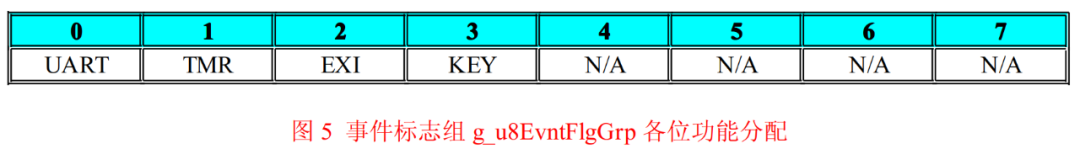
Thus, the system can extract four types of events: UART, TMR, EXI, and KEY, among which UART and KEY events must allocate buffers to store event-related data. All event detection is completed in their respective ISRs, and then the ISR notifies the main function to handle it.
To facilitate communication between the ISR and the main function, we define a global variable named g_u8EvntFlgGrp of type INT8U, referred to as the event flag group, where each bit represents a type of event. If the bit value is 0, it indicates that this type of event has not occurred; if the bit value is 1, it indicates that this type of event has occurred, and the main function must handle the event in a timely manner. Figure 5 shows the role of each bit in g_u8EvntFlgGrp.
Program Listing List9 shows an exemplary code written according to the above plan.
#define FLG_UART 0x01#define FLG_TMR 0x02#define FLG_EXI 0x04#define FLG_KEY 0x08volatile INT8U g_u8EvntFlgGrp = 0; /*Event Flag Group*/INT8U read_envt_flg_grp(void);/****************************************FuncName : main*Description : Main Function*Arguments : void*Return : void*****************************************/void main(void){ INT8U u8FlgTmp = 0; sys_init(); while(1) { u8FlgTmp = read_envt_flg_grp(); /*Read Event Flag Group*/ if(u8FlgTmp ) /*Are there any events occurring? */ { if(u8FlgTmp & FLG_UART) { action_uart(); /*Handle UART Event*/ } if(u8FlgTmp & FLG_TMR) { action_tmr(); /*Handle Timer Interrupt Event*/ } if(u8FlgTmp & FLG_EXI) { action_exi(); /*Handle External Interrupt Event*/ } if(u8FlgTmp & FLG_KEY) { action_key(); /*Handle Key Event*/ } } else { ;/*idle code*/ } }}/**********************************************FuncName : read_envt_flg_grp*Description : Read Event Flag Group g_u8EvntFlgGrp ,* After reading, it will be cleared.*Arguments : void*Return : void*********************************************/INT8U read_envt_flg_grp(void){ INT8U u8FlgTmp = 0; gbl_int_disable(); u8FlgTmp = g_u8EvntFlgGrp; /*Read Flag Group*/ g_u8EvntFlgGrp = 0; /*Clear Flag Group*/ gbl_int_enable(); return u8FlgTmp;}/**********************************************FuncName : uart0_isr*Description : uart0 Interrupt Service Function*Arguments : void*Return : void*********************************************/void uart0_isr(void){ ...... push_uart_rcv_buf(new_rcvd_byte); /*Store the newly received byte in the buffer*/ gbl_int_disable(); g_u8EvntFlgGrp |= FLG_UART; /*Set UART Event Flag*/ gbl_int_enable(); ......}/**********************************************FuncName : tmr0_isr*Description : timer0 Interrupt Service Function*Arguments : void*Return : void*********************************************/void tmr0_isr(void){ INT8U u8KeyCode = 0; ...... gbl_int_disable(); g_u8EvntFlgGrp |= FLG_TMR; /*Set TMR Event Flag*/ gbl_int_enable(); ...... u8KeyCode = read_key(); /*Read Keyboard*/ if(u8KeyCode) /*Is there a key operation? */ { push_key_buf(u8KeyCode); /*Store the new key value in the buffer*/ gbl_int_disable(); g_u8EvntFlgGrp |= FLG_KEY; /*Set TMR Event Flag*/ gbl_int_enable(); } ......}/**********************************************FuncName : exit0_isr*Description : exit0 Interrupt Service Function*Arguments : void*Return : void*********************************************/void exit0_isr(void){ ...... gbl_int_disable(); g_u8EvntFlgGrp |= FLG_EXI; /*Set EXI Event Flag*/ gbl_int_enable(); ......}
Take a look at the program listing List9; doesn’t this program structure resemble some programs you’ve written? For this implementation of the event-driven mechanism, we can even do better by forming a standard code template, creating a structure containing bit fields and an array of function pointers, where each element in the bit field serves as an event flag, and the function pointers array contains the addresses of each event handler function, each corresponding to each flag in the bit field.
In this way, the event handling code in the main() function can become standardized framework code. This implementation is quite good and can easily handle the vast majority of situations in practical applications. However, is this implementation of the event-driven mechanism really perfect? In my opinion, there are at least two issues with this implementation:
-
When different events occur simultaneously, it cannot record the order in which the events occurred.
-
When the same event occurs multiple times in quick succession, it is easy to miss the later occurrence of that event.
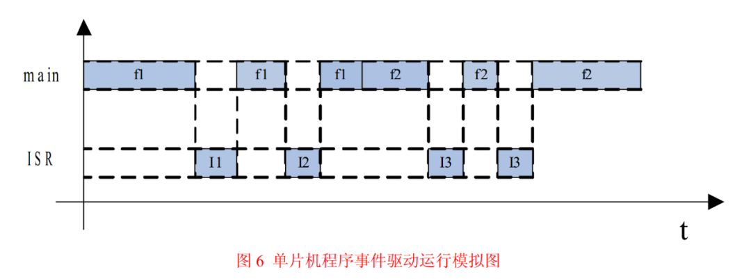
Figure 6 shows the execution situation of the microcontroller program during a certain period. In certain special cases, the two issues mentioned above can occur.
In the figure, f1 is the handler for a certain event, f2 is the handler for another event, and I1, I2, and I3 are three different events triggering ISRs, assuming that I1, I2, and I3 correspond to events E1, E2, and E3, respectively. From the figure, we can see that while the main function is calling the event handler f1, two events occurred, and the main function was interrupted twice by I1 and I2, each of which set their respective event flags.
After f1 returns, the main function calls another event handler f2. During the execution of f2, two occurrences of the same event happen in succession, and f2 is interrupted twice by I3, setting the corresponding event flags consecutively.
In Figure 6, we can certainly see that I1 executed before I2, meaning that event E1 occurred before event E2. However, when the main function reads the event flag group g_u8EvntFlgGrp again, it sees two flags that were “simultaneously” set, making it impossible to determine the order in which events E1 and E2 occurred. In other words, the information about the order of event occurrence is lost, which is the first issue mentioned: when different events occur simultaneously, it cannot record the order of occurrence.
In program listing List9, while the main function processes events, it does so in the pre-set order. If different events occur simultaneously during a certain period, there may be a discrepancy between the order of event occurrence and the order of event processing. If the system functionality is sensitive to the order of event occurrence, then the program in listing List9 would not meet the requirements.
Similarly, if I3 corresponds to event E3, which is like the EXI event in program listing List9 (this type of event does not have a buffering mechanism), the second occurrence of event E3 would be missed, which is the second issue mentioned: when the same event occurs multiple times in quick succession, it is easy to miss the later occurrence of that event.
If the system functionality is sensitive to the occurrence count of event E3, then the program in listing List9 would also not meet the requirements. Since the implementation of the event-driven mechanism has such flaws, is there a better implementation method? Of course! Transforming events into messages stored in a message queue can perfectly solve this problem; just hope you don’t mind my self-directed writing style.
Event-Driven and Messages
What are messages? Messages are a form of data storage for information. From the perspective of the program, a message is a memory block that stores specific data, and the data storage format is predetermined by the designer. As long as the memory is read according to the agreed format, useful information carried by the message can be obtained.
Messages are time-sensitive. Any message entity has a lifecycle, going through four stages from birth to death: generation, storage, dispatch, and consumption. The message entity is generated by the producer, stored and dispatched by the manager, and finally consumed by the consumer.
After being consumed by the consumer, the message ceases to exist. Although the original data may still remain in the memory storing the message entity, this data has no meaning for the system anymore, which reflects the timeliness of messages. At this point, have you noticed that the “message” here is quite similar to the “event” we’ve been discussing? It is very appropriate to apply the characteristics of “message” to “event”; in my view, messages are just a disguise for events.
When designing microcontroller programs, we all have a dream: to make the program respond to events as quickly as possible. Ideally, the program should respond to events immediately, without any delay. This is, of course, impossible; when an event occurs, the program will always be unable to respond immediately due to various reasons.
To avoid losing events, we can first process the events into messages in the ISR and store them in the message buffer. After completing these tasks, the ISR immediately exits. Once the main program finishes its other tasks, it can check the message buffer, read the messages stored by the ISR, analyze the information about the events, and then execute the corresponding response code to complete the response to the event.
As long as the time delay of the entire process is within the acceptable range for system functionality, this processing is fine. Transforming events into messages reflects the idea of trading space for time. By the way, although the ISR is triggered immediately after the event occurs, this is not a strict “response”; it can only be considered a “record” of the event. “Recording” and “responding” are different. Events are an objective existence, while messages are records of this objective existence.
For system inputs, events describe them in the time dimension, while messages describe them in the space dimension. Therefore, in describing the functionality of system inputs, events and messages are equivalent. Comparing with program listing List9, where global flags are used to record events, for certain special events, there are dedicated buffers to store additional information about the events, which cannot be recorded by global flags alone.
Now we use the message + message buffer method to record events, and the message buffer becomes a shared buffer for all events; regardless of whether the events that occurred have additional information, they are all stored in the buffer in the form of messages.
To record the order of event occurrences, the message buffer should be managed as a “first-in, first-out” circular buffer. The messages generated by events will always be enqueued from the tail, and when the management program reads the messages, it will always read from the head, ensuring that the order in which the messages are stored in the buffer represents the order of event occurrences in time, with earlier events always being responded to first.
After a message is read, the management program recycles the memory storing this message, inserting it as a free node at the tail of the buffer for future new messages.
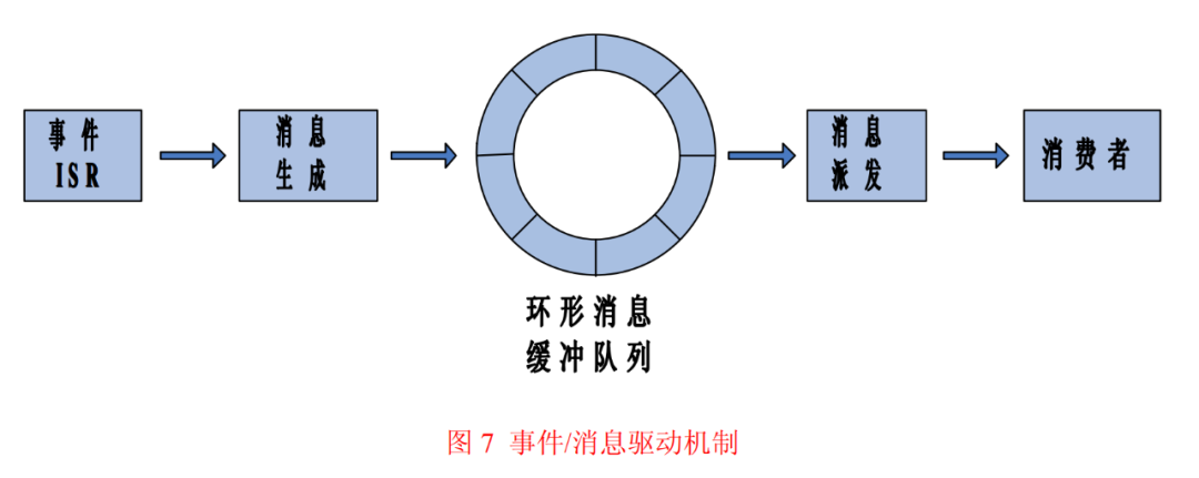
Figure 7 shows a schematic diagram of the event-driven mechanism using messages. I wonder if anyone has questions about the “consumer” in the figure; what does this “consumer” refer to in the program?
Since this event/message-driven mechanism serves the system application, the consumer naturally refers to the application layer code. To be more precise, the consumer is the state machine in the application code.
Using messages to implement the event-driven mechanism completely resolves the two issues mentioned earlier: when different events occur simultaneously, it cannot record the order of occurrences, and when the same event occurs multiple times in quick succession, it is easy to miss the later occurrences of that event. For the first situation, messages (events) are stored in the buffer in a “first-in, first-out” manner, and the storage order represents the order of event occurrences.
For the second situation, any event captured by the ISR will be stored as an independent message entity in the buffer, and even if the two events are the same, as long as the ISR reacts quickly, no events will be missed. In fact, the main task of the ISR is to fill in the message entity and then store it in the buffer. This task only takes a very short time of CPU usage.
Next, let’s discuss how to implement this message mechanism in the program. In the program, the message mechanism can be viewed as an independent functional module, and the implementation of a functional module is nothing more than data structure + algorithm. First, let’s look at the data structure of the message mechanism. Here, the data structure refers to the organizational form of data related to the message mechanism, consisting of two parts:
-
The data organization form of the message node itself
-
The data organization form of the message buffer
Program listing List10 shows the data structure of the message mechanism.
typedef union msg_arg /*Message Argument Union*/{ INT8U u8Arg; /*Member: 8-bit unsigned*/ INT8U s8Arg; /*Member: 8-bit signed*/ #if CFG_MSG_ARG_INT16_EN>0 INT16U u16Arg; /*Optional Member: 16-bit unsigned*/ INT16S s16Arg; /*Optional Member: 16-bit signed*/ #endif #if CFG_MSG_ARG_INT32_EN>0 INT32U u32Arg; /*Optional Member: 32-bit unsigned*/ INT32S s32Arg; /*Optional Member: 32-bit signed*/ #endif #if CFG_MSG_ARG_FP32_EN>0 FP32 f32Arg; /*Optional Member: 32-bit single precision float*/ #endif #if CFG_MSG_ARG_PTR_EN>0 void* pArg; /*Optional Member: void pointer*/ #endif}MSG_ARG;typedef struct _msg /*Message Structure*/{ INT8U u8MsgID; /*Message ID*/ #if CFG_MSG_USR_SUM > 1 INT8U u8UsrID; /*Consumer ID*/ #endif MSG_ARG uMsgArg; /*Application Message Argument*/} MSG;typedef struct msg_box /*Message Buffer Structure*/{ INT8U u8MBLock; /*Queue Lock Flag*/ INT8U u8MsgSum; /*Queue Length*/ INT8U u8MQHead; /*Queue Head Node Position*/ INT8U u8MQTail; /*Queue Tail Node Position*/ MSG arMsgBox[CFG_MSG_SUM_MAX]; /*Array to Store Queue*/} MB;static MB g_stMsgUnit; /*Global Variable for Message Management Unit*/
The data structure of the message contains two parts: the message header and the message parameters. In the message structure MSG, u8MsgID and u8UsrID are the message headers, while the union MSG_ARG is the message parameters.
u8MsgID is the type flag of the message, which is the event type flag that generated this message; the program selects the corresponding event handler function based on this member. u8UsrID is the consumer ID of the message; if there is only one consumer in the application code, the member u8UsrID can be ignored. MSG_ARG is the parameters attached to the message, which is the content information of the event.
Events in the system are diverse; some events only require a type flag, while others may need an integer variable to store event content, and some may require large memory blocks to store additional data. To unify the management of messages generated by various types of events, MSG_ARG must be able to store various types of data, so MSG_ARG is defined as a union.
From program listing List10, we can see that MSG_ARG can store 8-bit to 32-bit signed and unsigned integer data, single precision floating-point data, and void* type pointer variables, and the void* pointer can be forcibly converted into any type of pointer. Thus, MSG_ARG can store pointers to any type.
For certain members in MSG_ARG, precompiled constants CFG_MSG_ARG_XXX_EN are used for control. If these memory-consuming data types are not needed in actual applications, CFG_MSG_ARG_XXX_EN can be set to remove them. In the fully opened case, each message node occupies 6 bytes of memory, while in the most compact case, each message node occupies only 2 bytes.
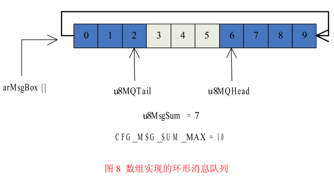
The global structure variable g_stMsgUnit is the data structure for the message buffer. The message buffer is a circular buffer, and here the circular queue is placed in a one-dimensional array, which is the member arMsgBox[] of g_stMsgUnit. The size of the array is controlled by the precompiled constant CFG_MSG_SUM_MAX, which is the maximum capacity of the circular buffer.
Theoretically, the larger the value of CFG_MSG_SUM_MAX, the better. However, considering the RAM resources of the microcontroller, the value of CFG_MSG_SUM_MAX should be a compromise between resource consumption and actual maximum demand, ensuring that there is still a margin in the circular buffer even in the worst case. Using an array to implement the circular queue also requires some auxiliary variables, which are the remaining members of g_stMsgUnit.
u8MBLock is the control variable of the queue; if u8MBLock > 0, it indicates that the queue is locked/protected and cannot be read or written. If u8MBLock = 0, it indicates that the queue is in normal state and can be read and written. u8MsgSum is the queue length counter, recording how many messages are currently stored in the queue; when a message is stored, u8MsgSum++ is executed, and when a message is read, u8MsgSum– is executed.
u8MQHead records the position of the current head message node in the array arMsgBox[], and its value is the index of the array element. The message read out is the one pointed to by u8MQHead; after reading it, u8MQHead moves one position towards the tail, pointing to the new head node; u8MQTail records the position of the current tail message node in the array arMsgBox[], and its value is the index of the array element. Before writing new messages, u8MQTail moves one position towards the tail, and then the new message is stored in the node pointed to by u8MQTail.
Figure 8 shows a schematic diagram of the global variable g_stMsgUnit of the message buffer structure.
Having established the data structure, we also need to implement the corresponding algorithm. The main body of the message mechanism is an array-based circular queue, and the algorithm of the circular queue is what we need. The message mechanism is an independent functional module that should shield its internal implementation details from the outside while only exposing a certain number of interface functions for external use. This is also the reason why I used the static keyword when declaring the g_stMsgUnit variable.
The message module has a total of 9 interface functions:
-
void mq_init(void) Initializes the message queue, responsible for initializing g_stMsgUnit.
-
void mq_clear(void) Clears the message queue, with the same effect as mq_init(), optional.
-
void mq_lock(void) Locks the message queue; a locked message queue cannot be read or written.
-
void mq_unlock(void) Unlocks the message queue, restoring normal functionality.
-
BOOL mq_is_empty(void) Checks if the message queue is empty; returns TRUE if empty, FALSE if there are messages stored.
-
INT8U mq_get_msg_cur_sum(void) Queries the total number of messages currently stored in the message queue; the function returns the query result.
-
INT8U mq_get_msg_sum_max(void) Queries the maximum capacity of the message queue; the function returns the query result.
-
INT8U mq_msg_post_fifo(MSG* pMsg) Sends a message to the message queue in a first-in, first-out manner. The parameter pMsg points to the backup memory of the message, and the function returns the operation result. This function is often called by ISR, so it must be a reentrant function.
-
INT8U mq_msg_req_fifo(MSG* pMsg) Reads a message from the message queue in a first-in, first-out manner. The function stores the read message in the memory pointed to by the parameter pMsg, and the function returns the operation result. This function is called by the main program and does not have to be a reentrant function, but it must protect shared data during critical sections.
The event/message-driven mechanism is a standard general framework that can handle any system input in conjunction with ISR. The event/message-driven mechanism shields the application layer program from the details of obtaining various system inputs, abstracting and integrating system inputs and submitting them to the application code for processing in a standardized format, greatly reducing the burden on the application layer code to obtain system inputs, allowing the application layer to focus solely on implementing high-level functionality.
From the perspective of software layering, the event/message-driven mechanism serves as an intermediate layer between the driver layer and the application layer. This layered structure is shown in Figure 9.
The reason there is still contact between the driver layer and application layer in Figure 9 is that when the system outputs a response, the application layer may still need to directly call the function interfaces provided by the driver layer. If a microcontroller software is structured like Figure 9, and if the application layer program uses state machines to operate under the drive of messages, then the design philosophy of this software is the theme of the entire article: a bare-bones general framework based on event/message-driven + state machine structure.
Program Framework: State Machine + Event/Message Driven
Event/message-driven and state machines are natural partners; this golden combination is a powerful tool for analyzing and solving problems.
Small Test
-
L1L2 state transition order OFF/OFF—>ON/OFF—>ON/ON—>OFF/ON—>OFF/OFF
-
Control the state of L1L2 through button presses; each state transition requires only one button press.
-
Start timing from the last button press; if there is no button event within 10 seconds, regardless of the current state of L1L2, it will always revert to the initial state.
-
The initial state of L1L2 is OFF/OFF.
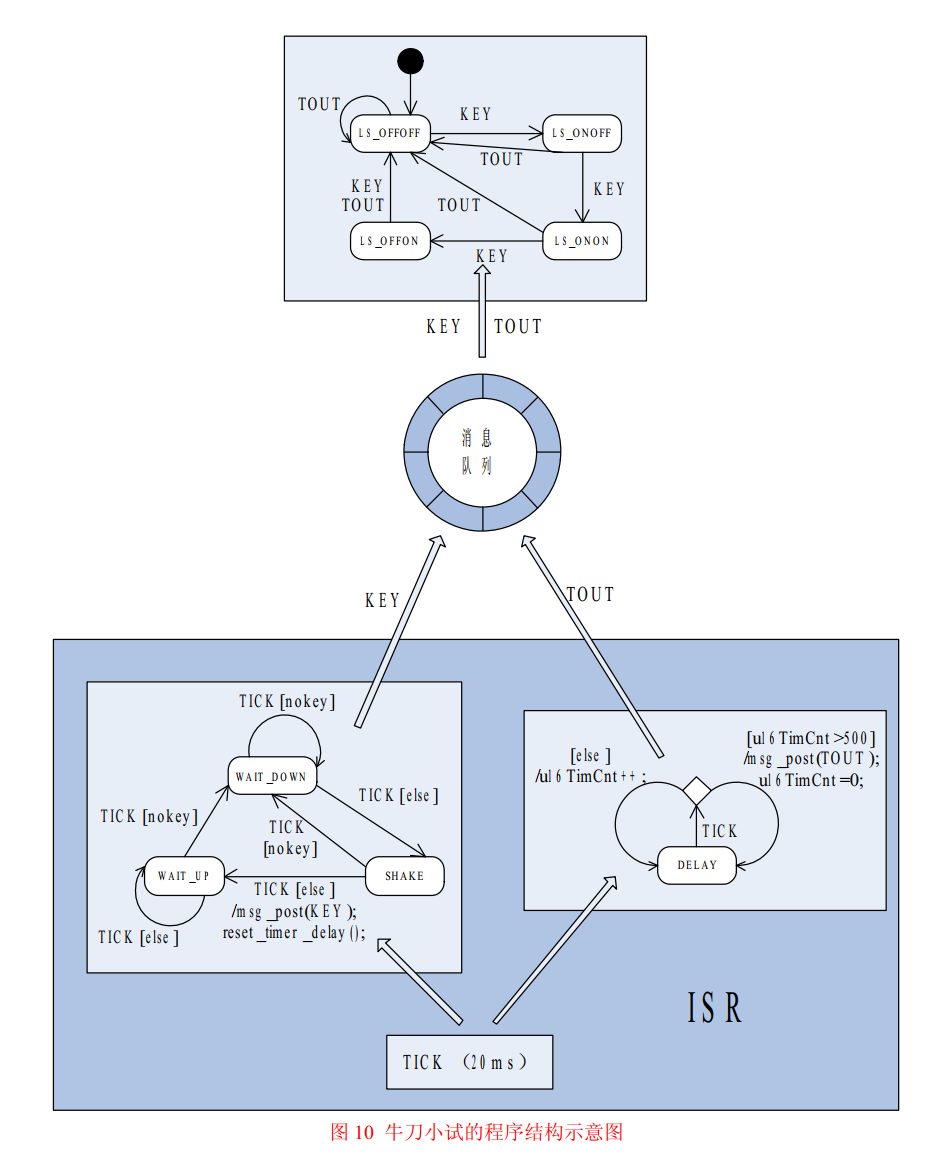
Now we will analyze the problem using the thoughts of state machine + event/message-driven. Two events can be extracted from the system: button event and timeout event, represented by event flags KEY and TOUT, respectively. The state and transition relationship of L1L2 can be made into a state machine called the main state machine, with four states: LS_OFFOFF, LS_ONOFF, LS_ONON, LS_OFFON. The main state machine will undergo state transitions driven by events KEY or TOUT, and the transition relationships between the various states are relatively simple, so we will skip that.
The task of the event/message-driven mechanism is to detect and monitor events KEY and TOUT and submit them to the main state machine for processing. Detecting button presses requires debounce processing, with a debounce time set to 20ms, and a timer is needed for the 10S timeout detection.
Here, the button detection program part is also made into a state machine with three states:
-
WAIT_DOWN: idle state, waiting for the button to be pressed.
-
SHAKE: initially detecting that the button is pressed, delaying for debounce.
-
WAIT_UP: debounce finished, confirming that the button has been pressed, waiting for the button to be released.
The transition relationships of the button state machine can be found in Figure 10. Both button detection and timeout detection share a timed interrupt with a period of 20ms, allowing the code for both detections to be placed in the ISR of this timer interrupt. I label this interrupt event as TICK. The button state machine operates under the drive of TICK; when the button is pressed and debounced, it triggers the KEY event, while the timeout detection counts TICK to trigger the TOUT event after 500 TICKs, indicating a 10S timeout.
With the above analysis, the structure of the program to achieve this functionality becomes very clear. Figure 10 is a schematic diagram of the structure of this program. This diagram is clear enough to express the problem, so I won’t write the specific code. Take a close look; doesn’t it seem to have some meaning?
If we ignore the details in the ISR of the timer interrupt, the entire program structure in Figure 10 is the event/message-driven + main state machine structure. The ISR serves as the message producer, while the program part related to message buffering and dispatching is the manager, and the main state machine is the consumer of the messages. In the application layer code, there is only this one state machine, which is the sole consumer of the messages.
This structure is the standard structure of the general framework GF1.0: multiple ISRs + one message buffer + one application layer main state machine. All messages (events) generated by the ISR are submitted to the main state machine for processing, and under the drive of messages, the main state machine continues to migrate.
If we consider the main state machine in the application layer as an engine, then the messages generated by the ISR are the fuel. As events continue to occur and messages continue to be generated, with the supply of fuel (messages), the engine (main state machine) can run continuously.
Next, let’s focus on the ISR in Figure 10. The contents of this ISR are quite rich, and it contains two small state machines: the button state machine and the timing state machine. The button state machine is self-explanatory, while the timing part can also be viewed as a state machine, but this state machine is special, having only one state, DELAY.
Since it is a state machine, it needs events to drive it. In this ISR, the interrupt event TICK serves as the drive for both the button state machine and the timing state machine. However, these two event-driven + state machine structures do not require message buffering, of course, because the state machine in the ISR responds to events immediately.
From a macro perspective, Figure 10 illustrates the event/message-driven + state machine structure, while from a micro perspective, the ISR in Figure 10 is also an event-driven + state machine structure. The state machine in the ISR generates messages (events) during its transitions, and these messages (events) become the driving events for the main state machine. The higher the level of the event, the more abstract it is, and the content it describes approaches human thinking. I believe this interwoven characteristic is the essence of the event-driven + state machine structure.
General Framework GF1.0
As mentioned earlier, state machines always passively accept events, and ISRs are only responsible for sending messages (events) into the message buffer. These messages are merely data and will not actively seek out the state machine. So how are the messages (events) stored in the buffer sent to the target state machine?
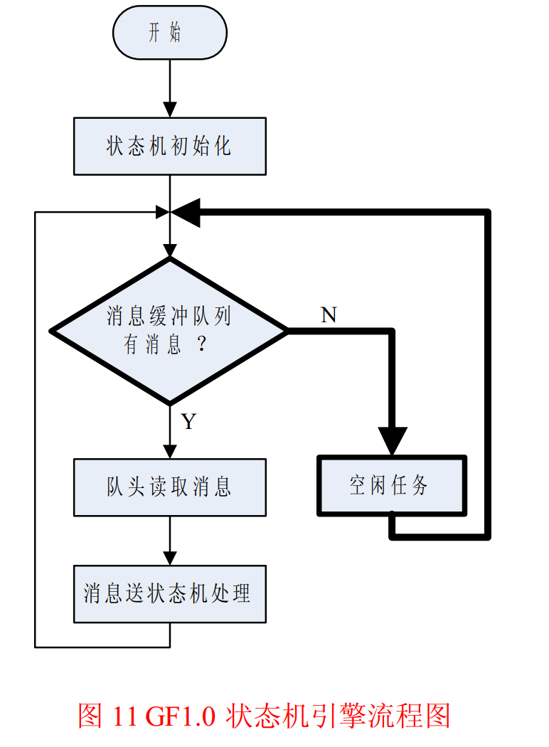
It is the task of the state machine scheduler to take messages from the buffer and send them to the corresponding state machine for processing. I refer to this part of the program as the State Machine Engine (SME). Figure 11 shows the general flowchart of the SME.
From Figure 11, we can see that the main job of the SME is to continuously query the message buffer queue. If there are messages in the queue, it retrieves them in a first-in, first-out manner and sends them to the state machine for processing. The SME processes only one message at a time, looping repeatedly until all messages in the message queue are processed.
When there are no messages in the message queue, the CPU enters an idle state, and the SME executes an “idle task.” Idle tasks refer to some work that is not critical to the implementation of key functions in the microcontroller system, such as feeding the watchdog, calculating CPU usage, etc. If one wants to reduce power consumption, the CPU can even enter a sleep state during idle tasks. As soon as an event occurs, the CPU will be awakened by the ISR and will execute the message processing code.
In practice, the CPU is idle most of the time during program execution, so the message queue querying and idle task portions of code are the most frequently executed parts of the program, as indicated by the bold frames and bold lines in the flowchart of Figure 11.
If the main state machine in the application layer is implemented using the compressed table driving method, combined with the message module provided above, the code for the GF1.0 state machine engine would be as shown in program listing List11.
void sme_kernel(void);/****************************************FuncName : main*Description : Main Function*Arguments : void*Return : void*****************************************/void main(void){ sys_init(); sme_kernel(); /*GF1.0 State Machine Engine*/}/****************************************FuncName : sme_kernel*Description : Bare-bones Framework GF1.0 State Machine Engine Function*Arguments : void*Return : void*****************************************/void sme_kernel(void){ extern struct fsm_node g_arFsmDrvTbl[]; /*State Machine Compressed Driving Table*/ INT8U u8Err = 0; /**/ INT8U u8CurStat = 0; /*State Temporary Storage*/ MSG stMsgTmp; /*Message Temporary Storage*/ struct fsm_node stNodeTmp = {NULL, 0}; /*State Machine Node Temporary Storage*/ memset((void*)(&stMsgTmp), 0, sizeof(MSG)); /*Variable Initialization*/ gbl_int_disable(); /*Disable Global Interrupts*/ mq_lock(); /*Lock Message Queue*/ mq_init(); /*Initialize Message Queue*/ mq_unlock(); /*Unlock Message Queue*/ fsm_init(); /*Initialize State Machine*/ gbl_int_enable(); /*Enable Global Interrupts*/ while(1) { if(mq_is_empty() == FALSE) { u8Err = mq_msg_req_fifo(&stMsgTmp); /*Read Message*/ if(u8Err == MREQ_NOERR) { u8CurStat = get_cur_state(); /*Read Current State*/ stNodeTmp = g_arFsmDrvTbl[u8CurStat]; /*Locate State Machine Node*/ if(stNodeTmp.u8StatChk == u8CurStat) { u8CurStat = stNodeTmp.fpAction(&stMsgTmp); /*Message Processing*/ set_cur_state(u8CurStat ); /*State Transition*/ } else { state_crash(u8CurStat ); /*Illegal State Handling*/ } } } else { idle_task(); /*Idle Task*/ } }}
Application of State Machines and ISR in Driver Programs
Using state machines and ISRs in driver layer programs can significantly enhance program efficiency. This advantage is most apparent in communication interfaces, such as serial port programs.
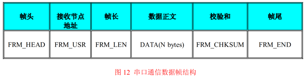
When microcontrollers communicate with the external world via serial port, data exchange is mostly done in the form of data frames. A complete data frame typically includes a frame header, receiving node address, frame length, data body, checksum, and frame tail. Figure 12 illustrates a common structure of such data frames.
This structure shown in Figure 12 is just a general common structure for data frames, and can be simplified as needed based on actual circumstances. For instance, if it is point-to-point communication, the receiving node address FRM_USR can be omitted; if the communication line is interference-free, ensuring correct data transmission, the checksum FRM_CHKSUM can also be omitted.
Let’s assume that a data frame does not exceed 256 bytes in length and that the number of communication nodes in the serial port network is less than 256. In this case, the frame header, receiving node address, frame length, and frame tail can all be represented using one byte each. Although the checksum may vary, using 1-4 bytes for the checksum is sufficient to meet requirements.
First, let’s discuss serial port reception. In the bare-bones framework GF1.0 structure, there are two possible implementations for serial port reception: ISR + message or ISR + buffer + message. ISR + message is relatively simple; when the ISR receives a byte of data, it sends that byte to the application layer program in the form of a message for subsequent processing. This processing method simplifies the structure of the serial port reception ISR and reduces its burden. However, it has two problems.
Data reception control is a very low-level function; according to the software layering structure, application code should not be responsible for these tasks, as mixing responsibilities can degrade the software structure. Additionally, using a message to transmit a single byte is inefficient and occupies too many message buffer resources. If the serial port baud rate is high and the message buffer is not large enough, it can lead to buffer overflow.
In contrast, the ISR + buffer + message processing method is much better. After the ISR receives a byte of data, it first places the data into a reception buffer. Once a complete frame of data is received (assuming the buffer is large enough), it sends the data to the application layer in the form of a message, allowing the application layer to read the data from the buffer.
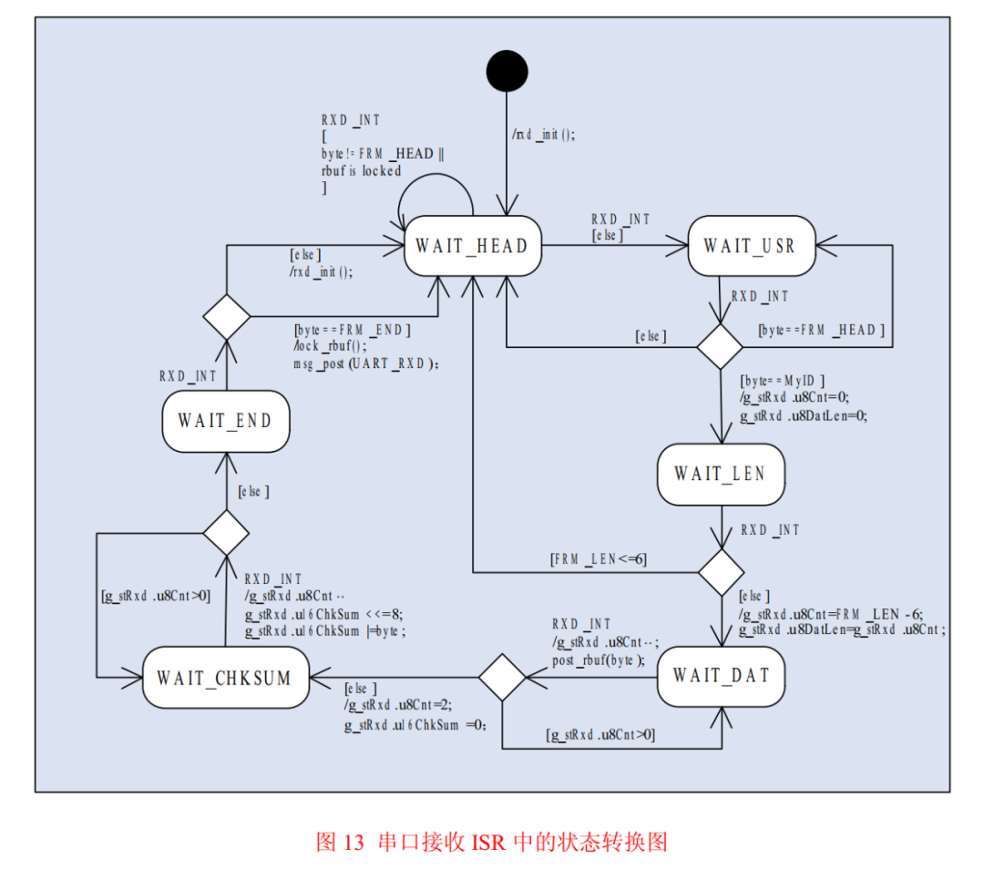
For the application layer, only the data body of the complete frame is the desired content; the remaining parts of the data frame are merely the wrapper for the data body and have no significance. From the perspective of functional division, ensuring correct data reception is the ISR’s responsibility, so this part of the task should be handled in the ISR. By pairing the serial port reception ISR with a state machine, the problem can be easily solved. Figure 13 shows the state transition diagram of the serial port reception ISR.
In Figure 13, the data frame uses a 16-bit checksum, with the high byte sent first, followed by the low byte. The reception buffer is a shared resource between the ISR and the main program, so mutual exclusion access must be implemented. After the ISR receives a complete frame of data, it locks the buffer, and any subsequent ISR that occurs after that locks the buffer so that no new data is received or modified.
Once the application layer program receives the message and reads the data from the buffer, it unlocks the buffer, allowing the ISR to continue receiving serial port data and writing to the buffer. After the data reception is complete, the data should be verified; only if the verification result matches the received checksum can we be sure that the data has been received correctly.
Data verification is time-consuming and not suitable for execution in the ISR, so it should be handled in the application code. The ISR for serial port reception is relatively complex and has a larger code size, which seems contrary to the principle of keeping ISR code as short and fast as possible. However, since the ISR contains a state machine, each time an interrupt occurs, the ISR only executes a small part of the entire code and then immediately exits, so the execution time is very short and will not be much slower than the “ISR + message” method.
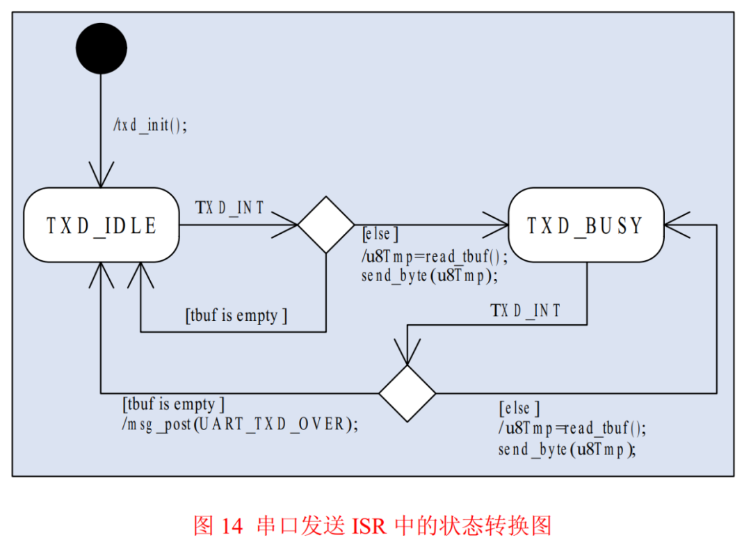
Serial port sending is much simpler than receiving. To improve efficiency, it is also implemented using the ISR + buffer + message method. When the program sends data, it calls the interface function provided by the serial port module, which retrieves the data to be sent through parameters, packages the data, and sends it to the sending buffer. The sending process is then automatically completed in cooperation with the hardware and the serial port sending ISR. Once all data has been sent, the ISR sends a message to the application layer, which can be used to inform the application layer of the completion of data transmission if needed. Figure 14 illustrates the state transition diagram of the serial port sending ISR.
The above discussion only covers the management methods for serial port devices. In fact, this state machine + ISR processing method can be applied to many hardware devices, including suitable scenarios such as:
-
Standard or homemade single-bus protocols (state machine + timer interrupt + message)
-
Using I/O to simulate I2C timing with low communication speed requirements (state machine + timer interrupt + message)
-
Dynamic scanning of digital tubes (state machine + timer interrupt)
-
Dynamic scanning of keyboards (state machine + timer interrupt)
Summary
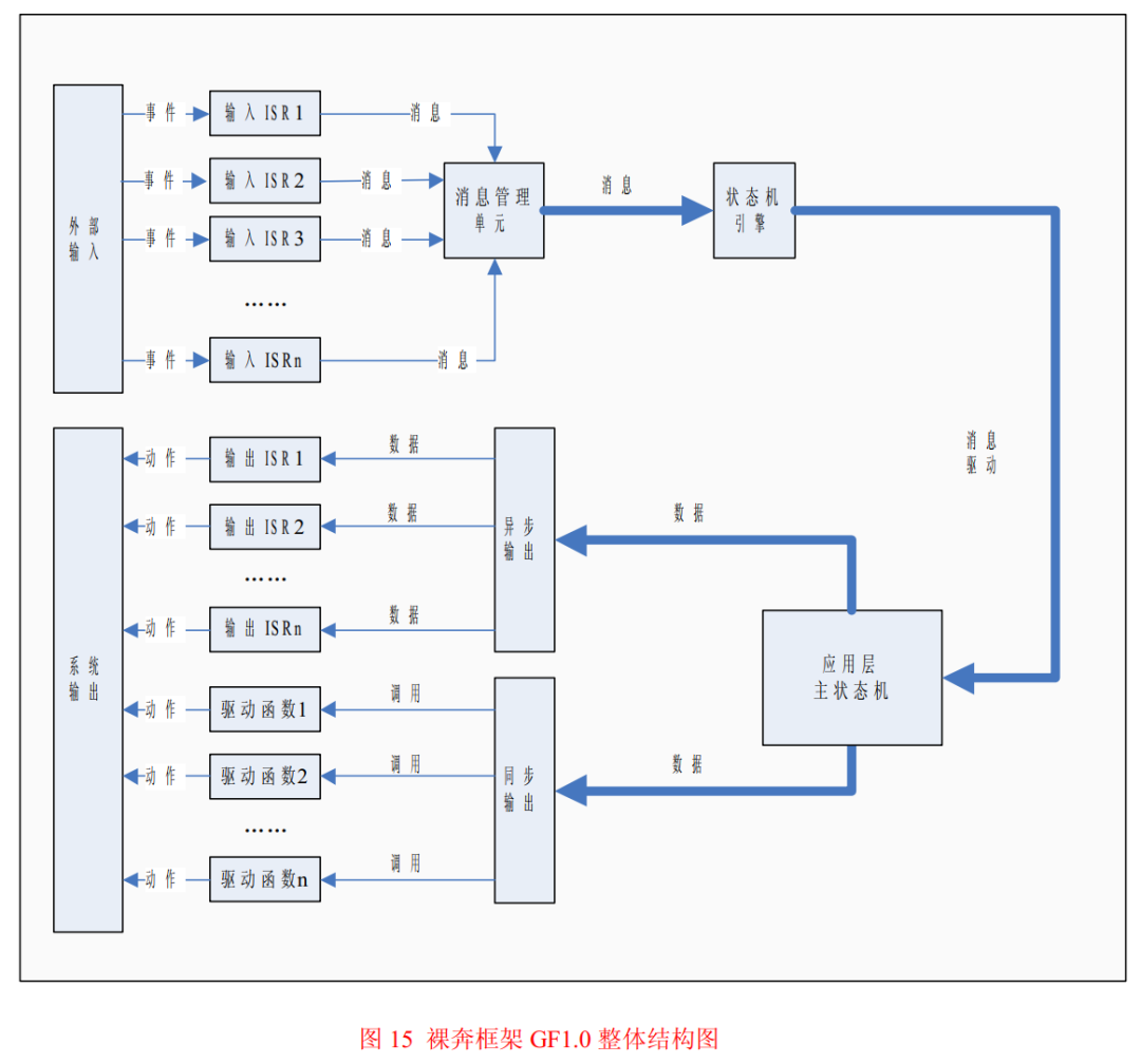
The bare-bones framework GF1.0 embodies the thoughts of event-driven + state machine throughout, from the overall organization structure of the program to the specific implementation of a certain ISR, the golden combination is present. From a macro perspective, the bare-bones framework GF1.0 is a structure of ISR + message management + main state machine, as shown in Figure 15.
Regardless of whether the main state machine uses FSM (finite state machine) or HSM (hierarchical state machine), there is only one main state machine in GF1.0. The main state machine is located in the application layer of the software and is the absolute core of the entire system, bearing the logic and computational functions. The interaction between the external world and the microcontroller system is actually the interaction between the external world and the main state machine, and all other parts of the microcontroller program are merely assisting the main state machine.
From a micro perspective, each ISR in the bare-bones framework GF1.0 is also structured as event-driven + state machine. The main task of the ISR is to reduce the burden on the main state machine to obtain external inputs. The ISR is responsible for handling the complex and detailed operations of obtaining inputs on the hardware level, abstracting various inputs, and submitting them to the main state machine in a standardized data format (message), allowing the main state machine to focus on implementing high-level functionality without worrying about specific details.
 The difficulty of applying the bare-bones framework GF1.0 lies in the specific implementation of the main state machine. For any practical application, regardless of how complex the functionality is, all these functionalities must be integrated into one main state machine. This requires the designer to have a sufficiently detailed understanding of the system’s target functionality, as well as a deep grasp of state machine theory. If the designed state machine is unreasonable, even if the other parts of the program are well designed, it cannot fully meet the system requirements.
Transforming practical problems into state machines requires reasonable state division and accurate extraction of system events, ensuring that none are missed or repeated. Once the states and events are established, the skeleton of the state transition diagram forms, and then the transition relationships between states are determined based on events, gradually refining from top to bottom until the entire functionality is realized.
The difficulty of applying the bare-bones framework GF1.0 lies in the specific implementation of the main state machine. For any practical application, regardless of how complex the functionality is, all these functionalities must be integrated into one main state machine. This requires the designer to have a sufficiently detailed understanding of the system’s target functionality, as well as a deep grasp of state machine theory. If the designed state machine is unreasonable, even if the other parts of the program are well designed, it cannot fully meet the system requirements.
Transforming practical problems into state machines requires reasonable state division and accurate extraction of system events, ensuring that none are missed or repeated. Once the states and events are established, the skeleton of the state transition diagram forms, and then the transition relationships between states are determined based on events, gradually refining from top to bottom until the entire functionality is realized.