▲ For more exciting content, click the blue text above to follow us
To become a qualified hardware engineer, mastering power supply knowledge is crucial—
Every operational system must have a power supply, and the reliability and stability of the power supply affect the entire system’s performance. So, how can we generate a “clean” power supply? What is the difficulty of DIYing a switching power supply, and what knowledge is required?
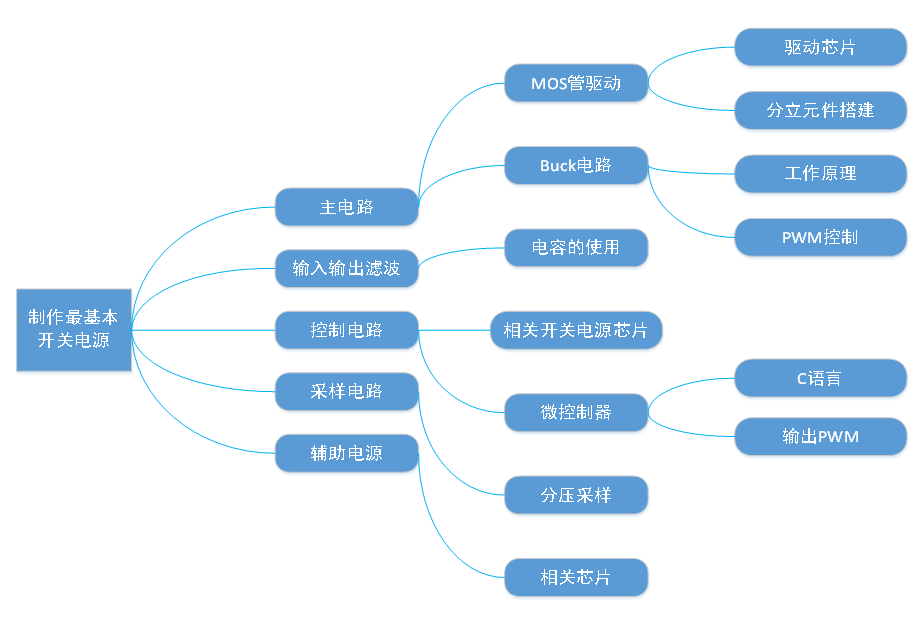
Complete Learning Path Breakdown
“
Don’t worry, let’s take it step by step, starting with the definition of switching power supply
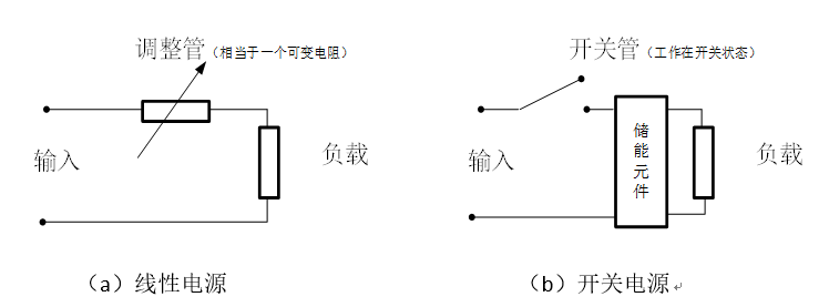
Figure 1: Two Common Power Supplies
As shown in the figure, the main classification of power supplies includes linear power supplies and switching power supplies. From the simplified diagram, (a) the linear power supply outputs a linear change with the size of the adjustment tube, while (b) shows the working principle of the switching power supply.
Why is it called a switching power supply? Simply put, a switching power supply uses modern power electronics technology to control the on-off time ratio of the switch tube, maintaining a stable output voltage.
In figures (a) and (b), besides simplifying the models of the two power supplies to clearly show their essential differences, the switching power supply and linear power supply also have the following differences:
1) The working mode of the power tube is different; the linear power supply’s power tube operates in a variable resistance state (amplification area), while the switching power supply’s power tube operates in a switching state (saturation and cutoff areas);
2) Efficiency differs. The linear power supply’s power tube acts as a variable resistor, which inevitably consumes electrical energy, while the switching power supply’s power tube operates in a switching state, resulting in higher efficiency, generally over 90%;
3) Ripple differs. The linear power supply has no switching action, resulting in low ripple noise, while the switching power supply has relatively high ripple noise;
4) The switching power supply is smaller in size and has a higher power output. The power tube of the linear power supply consumes electrical energy and thus generates more heat, requiring larger heat sinks, while the heat loss from the switching power supply’s power tube operating in a switching state is much smaller.
“
After clarifying the concept of switching power supplies, let’s look at the components of a switching power supply
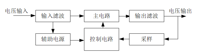
Figure 2: Basic Components of a Switching Power Supply
As shown in Figure 2, the working principle of the switching power supply is as follows: the input voltage is filtered and then converted by the main circuit into a pulsed voltage, which is then filtered again at the output to obtain the output voltage. At the same time, a sampling circuit is set up at the output to sample the output voltage and feed it back to the control circuit, which uses PWM modulation to control the state of the main circuit to achieve stable output voltage.
Each part of the basic components plays a significant role:
Input Filter: Removes noise from the input power grid, preventing noise generated by the device from feeding back into the grid;
Main Circuit: Plays the main role in voltage conversion, transforming the filtered input voltage into high-frequency DC pulsed voltage;
Output Filter: Filters out high-frequency noise generated by the switch tube in the main circuit, providing stable output voltage;
Sampling Circuit: Samples output voltage and current;
Control Circuit: Compares the sampled current data with reference data and generates control signals to control the main circuit for feedback control;
Auxiliary Power Supply: Provides working voltage for the control circuit.
“
After understanding the concepts and principles, let’s supplement the essential knowledge needed to make the simplest switching power supply
Many students, when starting DIY, often encounter blown capacitors, burned chips, and wasted MOSFETs… They flip through “Power Electronics Technology” books, learning what Buck is, what Boost is, what half-bridge is, carefully soldering boards, and making switching power supplies.
The fun of DIY lies here. Next, let’s prepare some essential knowledge points for making a switching power supply to help everyone avoid pitfalls when actually getting hands-on! (Note: We don’t need to set the power supply specifications too high at first; we just need to design a DC-DC power supply with constant voltage functionality for input DC and output DC.)
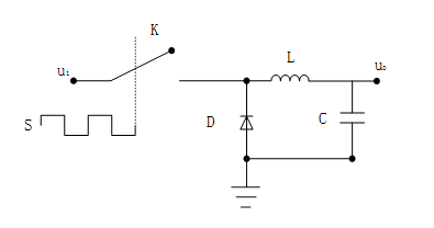
1) For the main circuit, you need to understand the Buck circuit, as shown in Figure 3. Understand its working principle and know that PWM (Pulse Width Modulation) controls its output voltage. It is recommended to refer to “Power Electronics Technology”.
Figure 3: Buck Circuit Schematic
2) For the input-output filter circuit, this part is easier. Understand that the voltage rating of the electrolytic capacitor must be higher than the applied voltage to avoid explosion. To achieve good filtering effect, multiple capacitors should be connected in parallel, and both electrolytic and ceramic capacitors should be used together since ceramic capacitors have good high-frequency characteristics and can effectively filter out high-frequency noise. Meanwhile, electrolytic capacitors have large capacity, which helps maintain stable output voltage.
3) For the control circuit, if using a dedicated switching power supply chip, follow the typical circuit provided in the reference chip manual. If using a microcontroller, knowledge of C language is required, as well as understanding how to control the microcontroller’s pins to output PWM waves and the driving circuit for MOSFETs.
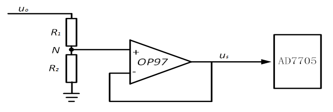
4) For the sampling part, you need to understand resistor voltage divider sampling, as shown in the circuit diagram below:
Figure 4: Voltage Divider Sampling Circuit
In the figure, OP97 mainly serves to protect the subsequent circuit. Without OP97, directly connecting point N to the subsequent circuit could lead to the voltage at point N exceeding the tolerable voltage of the subsequent circuit, potentially burning out the AD converter or other subsequent circuits. With OP97, if the voltage at point N becomes too high, OP97 will enter the saturation region, limiting the output voltage to the working voltage, preventing damage to the subsequent circuit.
5) For the auxiliary power supply, you can directly use relevant power supply chips (if the control circuit uses integrated switching power supply chips, the auxiliary power supply is generally integrated within the chip).
6) We recommend using a microcontroller for the control part, building the main circuit with MOSFETs, and using relevant switching power supply chips for the auxiliary power supply, such as ADI’s ADP2360 or LTC3309.
If using integrated switching power supply chips, the part you need to make is minimal; just add a few resistors, capacitors, and inductors according to the chip manual. However, if using a microcontroller, you will need to design and select components for the main circuit, sampling circuit, driving chips, and auxiliary power supply chips, which provides a deeper learning experience.
Recommended Reading
DIY | An Expert Analyzes Power MOSFETs This Way, Rare Material!
DIY | This Might Be the Most Comprehensive Common Electronic Interface Guide!
DIY | Why Is Impedance Matching Important? How to Perform Impedance Matching?
DIY | 104 PCB Layout and Wiring Tips Q&A
In the public account, reply with any content you want to search, such as keywords, technical terms, bug codes, etc., to easily obtain related professional technical content feedback. Give it a try!
Due to recent changes in WeChat public account push rules, if you want to see our articles regularly, please click “Like” or “View” at the bottom of the page after reading each time; this way, the articles pushed each time will appear in your subscription list promptly.
Alternatively, set our public account as a star. After entering the public account homepage, click the upper right corner “three small dots”, and click “Set as Star”; a yellow pentagram will appear next to our public account name (Android and iOS users operate the same).
Focus on industry hotspots, stay updated with the latest frontiers
Please follow EEWorld Electronic Headlines
http://www.eeworld.com.cn/mp/wap
Copy this link to your browser or long press the QR code below to browse
The following WeChat public accounts belong to
EEWorld (www.eeworld.com.cn)
Welcome to long press the QR code to follow!
EEWorld Subscription Account: Electronic Engineering World
EEWorld Service Account: Electronic Engineering World Welfare Society