01
What is RS-485
RS-485 is an industrial standard that defines the electrical interface and physical layer for point-to-point communication between electrical devices.The RS-485 standard allows for longer wiring distances in electrically noisy environments and can support multiple devices on the same bus.
RS-485 has been used in widespread computer automation systems since the standard was created in 1998.Because the standard allows for multipoint (multiple devices on the same bus) and longer cable lengths, it is easy to understand its frequent use in industrial and automation fields.
RS-485 can also be seen in theater applications where many devices are distributed over large spaces.Additionally, the noise immunity provided by the RS-485 standard makes the interface very versatile.Engineers use it not only for long-distance wiring but also in applications such as the automotive industry, where it is uncertain what kind of noise may be encountered in the final application.
RS-485 can be used in high-speed, long cable lengths, electrically noisy environments, and with multiple devices on the same bus, making it an intelligent implementation for most applications requiring serial interfaces.
02
RS-485 Standard
RS-485, also known as TIA-485 or EIA-485, defines the electrical characteristics of drivers and receivers for communication protocols.The Open Systems Interconnection (OSI) model attempts to describe the various layers of a communication system, from the end application to the electrical layer, and finally to the physical layer, as shown in Figure 1.
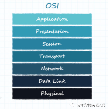
Figure 1: OSI Model of Communication
03
Physical Layer of the OSI Model
1. Topology
The physical layer of the OSI model is responsible for transmitting raw data between devices and the physical transmission medium, it handles the conversion from electrical signals to digital data while defining voltage, timing, data rates, etc.
The two signal lines used by RS-485, “A” and “B”, must be balanced and differential.A balanced signal shares a pair of lines in twisted pair cable, with equal impedance on each line.In addition to the matched impedance of the lines, the receiver and transmitter must also have matched impedance.
Figure 2 shows a typical multipoint RS-485 network, where each device has a differential RS-485 transceiver, and the links between devices consist of twisted pair cable and termination resistors.
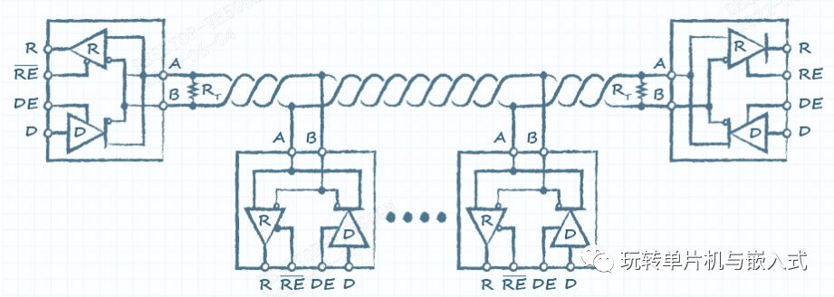
Figure 2: Topology of RS-485 Bus
Note that there are various topologies available for arranging devices on the RS-485 bus, as not all networks are equal, and termination requirements and device arrangements may vary.For example, in Figure 2, termination is only used at the beginning and end of the cable.
2. Differential Signals
Balanced wiring can reduce noise when using differential signals, these signals “A” and “B” are called differential signals.One signal matches the original signal, while the other is completely inverted, which is why it is sometimes referred to as a complementary signal.
In single-ended interfaces, the receiver grounds the signal and interprets the signal state based on predetermined voltage levels (these are called logic levels as they determine whether the signal is logic high or logic low).
However, signal errors often occur over longer cable distances where voltage tends to drop and slew rates decrease.
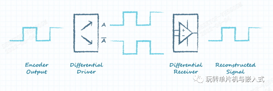
In differential applications, the host generates the original single-ended signal and then sends it to the differential transmitter.This transmitter creates a differential pair to send out through the cable.After generating the two signals, the receiver no longer references the voltage levels to ground but references the signals to each other.This means that the receiver is not looking for specific voltage levels but is always looking at the difference between the two signals.
Then, the differential receiver reconstructs this pair of signals back into a single-ended signal, which the host device can use to interpret using the appropriate logic levels required by the host, as shown in Figure 3, this type of interface also allows devices with different voltage levels to operate by connecting them through differential transceivers, all of which work together to overcome signal attenuation that may occur in single-ended applications over long cable distances.
3. Differential Signals Against Interference
Signal attenuation is not the only problem that occurs over long cable distances. The longer the cable is within the system, the greater the likelihood of electrical noise and interference entering the cable and ultimately the electrical system. When noise couples onto the cable, it appears as voltage of varying amplitudes, but the benefit of using balanced twisted pair cable is that noise couples equally onto both lines of the cable. For example, a positive 1V spike will result in +1V on A and +1V on B.
Since the differential receiver subtracts the signals from each other to obtain the reconstructed signal, it ignores noise that appears equally on both lines, as shown in Figure 4.The ability of the differential receiver to ignore the same voltage on both signal lines is known as common-mode rejection.
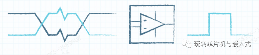
Figure 4
4. Wide Voltage Range
Another major physical layer advantage of RS-485 is the signal voltage specification.RS-485 does not require a specific bus voltage but specifies the minimum differential voltage required, which is the difference in voltage between signals A and B.
The total line requires a minimum differential voltage of ±200mV for the receiver, and typically all RS-485 devices will have the same input voltage range, although they may transmit at different voltages.This means that any RS-485 device can receive a voltage range of -7 to 12V. Therefore, engineers can design host systems with any transmission voltage within that range.This allows designers to create RS-485 systems using the voltage of their existing circuit boards.
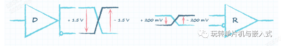
Figure 5
04
Data Link Layer of the OSI Model
RS-485 is a duplex communication system where multiple devices on the same bus can communicate bidirectionally.RS-485 is most commonly used as half-duplex, as shown in the above figure, with only one communication line (“A” and “B” paired).In half-duplex, devices take turns using the same line, where the host asserts control over the bus and sends commands, while all other devices listen.The receiver will listen for its address, then that device will assert control and respond.
Conversely, in a full-duplex system, such as the Serial Peripheral Interface (SPI) or Universal Asynchronous Receiver-Transmitter (UART), the host and slave devices can communicate simultaneously using dedicated input and output lines.
At the data layer, RS-485 typically uses UART for serial communication, with the host UART driving and receiving serial communication in full-duplex mode.It connects to the RS-485 differential transceiver that makes up the physical layer and converts the signals into half-duplex differential format for use on the RS-485 bus.The host then communicates with RS-485 via UART, instructing the transceiver when to switch between sending and receiving, while the slave devices will also use their UARTs in the same manner.
UART has dedicated transmit and receive lines, allowing it to operate in full-duplex, half-duplex, or even simplex modes. This means that data can only be output or input through one line.Since RS-485 is typically half-duplex, the UART connected to it will also operate in half-duplex mode.
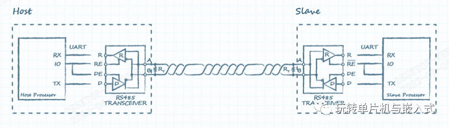
Figure 6
The main processor will use IO pins to place the RS-485 transceiver in transmit mode and send a byte from the UART TX line to the RS-485 transceiver’s data (D or DI) line. The transceiver will convert the single-ended UART bit stream into a differential bit stream on the A and B lines. After the data leaves the transceiver, the host immediately switches the transceiver mode to receive.
The slave system is the same, meaning the slave RS-485 transceiver receives the incoming bit stream, converts it to a single-ended signal, and sends it to the host device via the slave’s UART RX line.When the slave device is ready to respond, it will send as the host initially did, while the host now receives, as shown in the following figure.
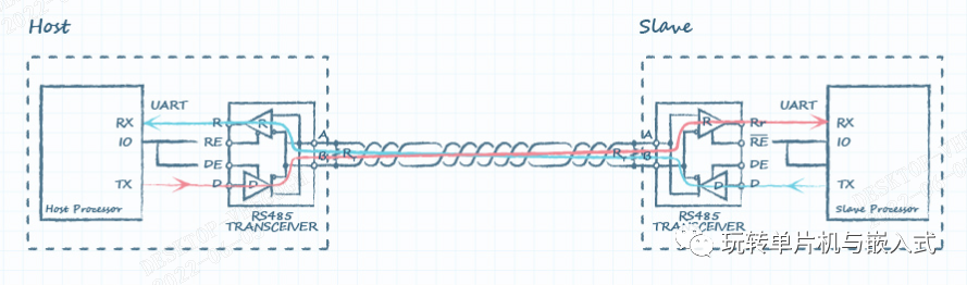
Figure 8
05
Network Layer of the OSI Model
The network layer handles the actual communication between devices on the RS-485 bus.Since RS-485 is primarily an electrical specification, the dialogue could end here, but because it supports multipoint, it needs to be addressed in the OSI model.
There is no fixed specification for addressing at the network layer, but the RS-485 bus must be properly managed by the host to avoid bus conflicts.A bus conflict occurs when multiple devices attempt to communicate simultaneously, which can be very damaging to the network.
When a conflict occurs, the transmitters short-circuit at both ends, effectively creating a short circuit.This can cause each device to draw excessive current, putting the transceivers into thermal shutdown.To avoid conflicts, the host controls the bus and calls each device.This is usually achieved by having a command set that only specific devices can recognize or by providing each device with a specific address.
Since the bus is shared among all devices, each device will see the command/address sent by the master device, but only that single device will respond when it is asserted.
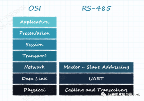
Figure 9
06
Application Layer of the OSI Model
The OSI model is not a set of rules but more of a model to help engineers characterize systems.RS-485 fits well within the first three layers of the OSI model, and the actual implementation of the bus is characterized at the application layer.This layer encompasses the addresses or command sets used by devices, as well as the interpretation of data. Additionally, it includes how much data designers expect to receive and the control over the bus itself.
For example, the application for CUI Devices RS-485 encoders would be the host requesting the absolute position from the device.When the host sends the encoder’s position command (address), the encoder responds with two complete bytes.The host then decrypts these bytes to understand what the absolute position is, while determining the frequency at which it wants to send commands and to which devices.In simple terms, the application layer is the implementation of the RS-485 bus.
Since the RS-485 standard only defines the physical and data link layers with addressing requirements, the application layer can adopt various proprietary or open communication protocols.Engineers can use existing protocols like Modbus, or they can define their own protocol for their applications.For example, CUI Devices’ encoders use a very simplified addressing structure to assert devices, enabling quick turnaround and minimal processing time.The address for each encoder consists of the high six bits of one byte, with the low two bits being the command.This allows the encoder to begin responding after a single byte from the host, ensuring a quick turnaround time, which is crucial in motion control applications.
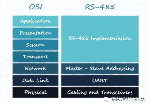
Figure 10
07
Conclusion
To summarize,RS-485 supports high speed, long cable distances, electrical noise tolerance, and multiple devices on the same bus. Due to its versatility in widespread applications, it has become a popular serial interface in rotary encoders.
Designers using encoders with RS-485 interfaces hope to benefit from an understanding of the details above, including its various layers, implementations, and best practices in system communication.
Due to recent changes in WeChat public account push rules, many readers have reported not seeing updated articles in a timely manner. According to the latest rules, it is recommended to click on “Recommended Reading, Share, Favorite,” etc., to become a frequent reader.
Recommended Reading:
-
The Several Realms of Hardware Development, How Far Have You Cultivated?
-
Another Executive of the Big Fund Investigated, Involving Several Listed Companies!
-
Confirmed! Another Plot of the US NSA’s Cyber Attack on Xi’an University of Technology Exposed
Please click 【View】 to give the editor a thumbs up
