
Follow for More Insights

As the core device in industrial automation control, mastering Siemens PLC programming techniques is crucial for improving production efficiency. This article will introduce some commonly used PLC programming tips from a practical perspective to help everyone better utilize PLCs for various control functions.
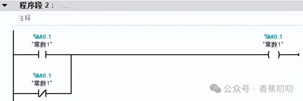
Clever Use of Normally Closed and Normally Open Contacts
In PLC programming, normally closed and normally open contacts are two very useful “helpers”.
Normally Closed Contacts can be used as a logic branch disconnection, a shielding switch for debugging or maintenance. For example, when debugging a certain function, you can temporarily shield other irrelevant logic using normally closed contacts and remove them after debugging is complete.
Normally Open Contacts can serve as a logic branch connection, a switch for debugging or maintenance. They are very useful when you need to force a certain function to operate.
When using these two contacts, it is recommended to choose relatively independent memory locations to avoid conflicts with other functions.
Utilizing Power-Up Pulses for Initialization
Power-up pulses are brief pulse signals generated by the PLC each time it is powered on. We can use this pulse to perform system initialization operations, such as resetting counters, clearing accumulators, and setting key parameters.
This ensures that every time the system starts, it is in a known initial state, avoiding state confusion caused by abnormal shutdowns.
One-Button Start/Stop Function Implementation
When the number of buttons is limited, you can implement the start and stop functions using one button through programming. The core idea is:
-
Detect the rising edge of the button press
-
Switch between start/stop based on the current system running state
-
Use a self-locking circuit to maintain the state
This method can effectively save panel space and is very practical when the number of operation buttons is insufficient.

Calibration Techniques for Analog Inputs and Outputs
When dealing with analog signals, numerical conversion is often required. The following two functions can greatly simplify this process:
Analog Input Calibration: Calibrating integer analog values to real engineering quantities. Analog Output Calibration: Calibrating real engineering quantities to integer digital values.
These two functions are similar to the SCALE_X and NORM_X functions in TIA Portal software but add high and low range limits, making calibration and debugging more convenient.
Below is an SCL code example for analog input calibration:
IF (#Emin < #Emax) AND (#Dmin < #Dmax) THEN
IF #Raw < #Dmin THEN
#RawTemp := #Dmin;
END_IF;
IF #Raw > #Dmax THEN
#RawTemp := #Dmax;
END_IF;
IF (#Raw >= #Dmin) AND (#Raw <= #Dmax) THEN
#RawTemp := #Raw;
END_IF;
#OutReal := (INT_TO_REAL(#RawTemp - #Dmin) / INT_TO_REAL(#Dmax - #Dmin)) * (#Emax - #Emin) + #Emin;
#OutPercentage := (#OutReal / (#Emax - #Emin)) * 100.0;
ELSE
#OutReal := 0.0;
#OutPercentage := 0.0;
END_IF;
This code converts the raw analog value (#Raw) into the actual engineering quantity (#OutReal) and percentage value (#OutPercentage). It also handles input value limits to avoid exceeding the measurement range.
Implementing Array Sorting Functionality
In certain applications, we may need to sort a set of data. Below is an SCL code example that implements array sorting using the bubble sort method:
IF #Enable THEN
#L := LOWER_BOUND(ARR := #Array, DIM := 1);
#H := UPPER_BOUND(ARR := #Array, DIM := 1);
FOR #i := #L TO #H-1 DO
FOR #j := #L TO #H-1-#i DO
IF #Mode THEN
//Ascending
IF #Array[#j] > #Array[#j + 1] THEN
#temp1 := #Array[#j];
#Array[#j] := #Array[#j + 1];
#Array[#j + 1] := #temp1;
END_IF;
ELSE
//Descending
IF #Array[#j] < #Array[#j + 1] THEN
#temp1 := #Array[#j];
#Array[#j] := #Array[#j + 1];
#Array[#j + 1] := #temp1;
END_IF;
END_IF;
END_FOR;
END_FOR;
END_IF;
This code allows sorting in ascending or descending order based on the #Mode parameter. After sorting, the original array will be directly modified.
Application of Ramp Function
The ramp function allows the output value to follow the setpoint change at a specified slope (units/second). This is very useful in situations that require smooth transitions, such as motor speed adjustments and temperature control.
Below is a simplified SCL code for the ramp function:
#DeltaTime := TIME_TO_REAL(T_DIFF(IN1 := #ActualTime, IN2 := #LastTime)) / 1000.0;
#LastTime := #ActualTime;
IF #SetPoint < #AuxOut THEN
#auxR := #AuxOut - (#Rate * #DeltaTime);
#AuxOut := MAX(IN1 := #auxR, IN2 := #SetPoint);
ELSIF #SetPoint > #AuxOut THEN
#auxR := (#Rate * #DeltaTime) + #AuxOut;
#AuxOut := MIN(IN1 := #auxR, IN2 := #SetPoint);
END_IF;
#Out := #AuxOut;
This code allows the output value (#Out) to approach the setpoint (#SetPoint) at a rate not exceeding the specified #Rate.
Practical Application Case: Material Transport Vehicle Control System
To better understand the application of PLC programming techniques, let’s look at a practical case of a material transport vehicle control system.
The transport vehicle is driven by a three-phase AC asynchronous motor and can run left and right. Control requirements include:
-
Jog control: Runs when the corresponding button is pressed
-
Continuous control: Runs continuously after pressing the start button until the stop button is pressed
-
Interlocking functions for both hardware and software
Below is a ladder diagram program example written using contact instructions:
|   Jog Forward    |                      |  Forward Output  |
|——| |————————————————————————————————( )——————|
|              |                      |           |
|   Continuous Forward    |  Forward Self-Lock    Reverse Output  |           |
|——| |——————|——| |————————| /|————————|           |
|              |                      |           |
|   Jog Reverse    |                      |  Reverse Output  |
|——| |————————————————————————————————( )——————|
|              |                      |           |
|   Continuous Reverse    |  Reverse Self-Lock    Forward Output  |           |
|——| |——————|——| |————————| /|————————|           |
|              |                      |           |
|     Stop      |  Forward Self-Lock  |  Reverse Self-Lock |           |
|——| /|——————————(R)———————(R)————————|           |
This program implements both jog and continuous running functions while ensuring that forward and reverse cannot occur simultaneously through interlocking.
Considerations:
-
In practical applications, it is also necessary to consider adding limit switches and other safety protection measures
-
For high-power motors, it is recommended to add soft start or inverter control to reduce impact on the power grid
-
Regularly check and maintain the mechanical parts to ensure safe and reliable operation
Practical Recommendations
Mastering these PLC programming techniques requires continuous practice and experience. It is recommended to start with simple control tasks and gradually increase complexity. You can use PLC simulation software for initial debugging and then verify on actual hardware. Record the problems encountered and solutions to build your own knowledge base. Maintain enthusiasm for learning new knowledge and keep up with the latest developments in PLC technology.
Give a Like

Let’s Go Again