In the coal chemical industry, processes such as coal supply, air separation, gasification, synthesis, and desulfurization are all contained within individual workshops. For example, a typical coking plant generally includes a coal preparation workshop, coking workshop, recovery workshop, coke oven gas and tar processing workshop, benzene processing workshop, desulfurization workshop, and wastewater treatment workshop.
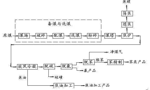
Coking Plant Production Process Flow
1Coal Preparation and WashingProcess Description
Raw coal generally contains a high ash and sulfur content. The purpose of washing is to reduce the ash content of the coal and separate the mixed gangue and coal according to their relative density, shape, and physical properties. At the same time, the inorganic sulfur content in the raw coal is reduced to meet the quality standards required by different users.
Due to the variety of power equipment in the coal washing plant and the complexity of the control process, a distributed control system (DCS) is used to transform the traditional coal washing process. This is significant for improving the automation of the washing process, reducing the labor intensity of workers, increasing product yield and quality, and ensuring safe production.
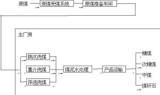 Coal Washing Plant Process Flow Diagram
Control Scheme
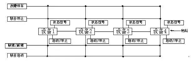
Coal Washing Plant Motor Sequence Start/Stop Control Flow Chart
Interlock/Unlock Scheme:In the running unlock state, individual start or stop of each device is allowed; when set to interlock state, pressing the start button will start the devices in sequence, where the start of the latter device depends on the successful start of the previous device (the delay start time between devices can be set). If the previous device fails to start successfully, the latter device cannot start. Pressing the stop button will stop the devices in sequence. During operation, if one device fails and stops, for example, device 2 stops, the system will stop devices 3 and 4, but device 1 will continue to run.
2Coke Oven and Cold Drum
(Taking the reflux coking device as an example, the process flow is briefly described as follows)
Process Description
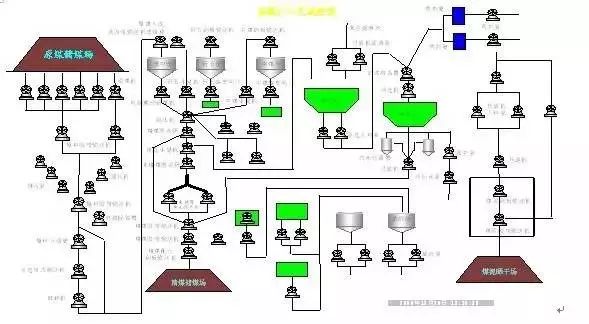
With an annual output of 1 million tons – 144 holes – double furnace – 4 gas collection pipes – 1 large reflux coking device
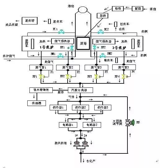
1 Million Tons/Year Coke Oven Cold Drum Process Flow Diagram
Control Scheme
The typical coking process can be divided into two sections: the coke oven and the cold drum. These two sections have distinct roles yet are interrelated. They are also geographically distanced to avoid long-distance wiring for instruments, setting up a cold drum remote station and a water supply remote station, allowing the instrument lines to enter the DCS control cabinet nearby. More importantly, in the pressure regulation of the gas collection pipe, there is an important interlock and queuing relationship between the two stations, and this network structure facilitates complex control algorithms.
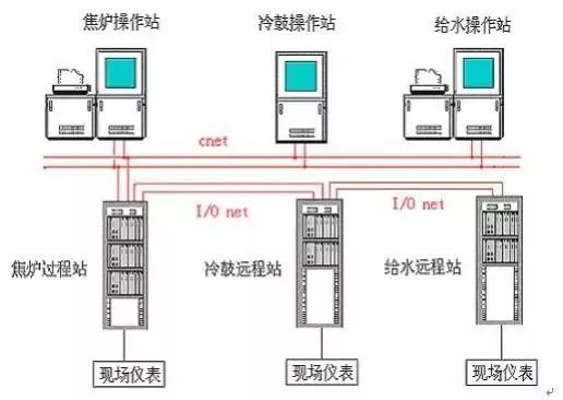
Control System Network Structure
Gas Collection Pipe “4+1” Optimization Control Scheme
In the diagram, P1 to P4 represent the gas collection pressure values, which are the focus of this system control. P is the average value of the gas collection pipe pressure, reflecting the general working state of the gas collection pipe. In the “4+1” control (“4” represents the four gas collection pipes, and “1” represents the selection of either the large reflux regulating valve RB or the hydraulic coupling EF control, with one of the two selected), the time distributor adjusts the large reflux and hydraulic coupling adjustment amount based on the variations in gas collection pipe pressure: deviation and deviation change rate, considering the slow characteristics of the hydraulic coupling speed regulation. The characteristics of gas collection pipe pressure variations are significant transient changes, with mutual coupling during adjustments. This control algorithm design includes a decoupling algorithm to reduce or eliminate coupling, ensuring that each single-loop system can operate independently. This control algorithm employs an optimized control method combining classical control theory with discrete control theory, achieving good control results.
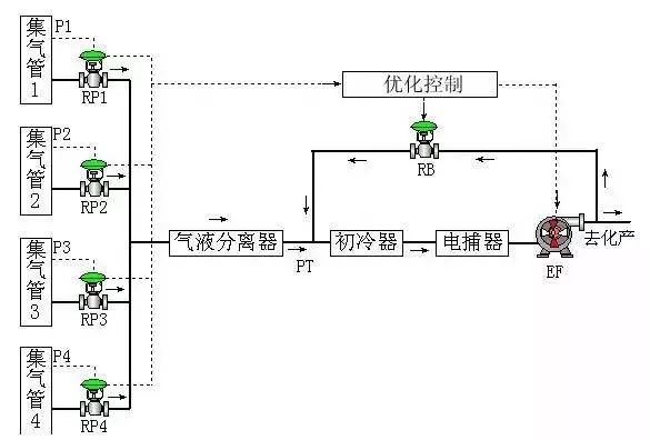 Gas Collection Pipe Pressure Regulation Optimization Control Diagram
Interlock Scheme
The alarm, interlock, and shutdown systems are special procedures set to enhance the safety of the process production equipment. This control system divides the interlock control into three parts: cold drum section interlock control, blower interlock control, and blower oil pump interlock control.
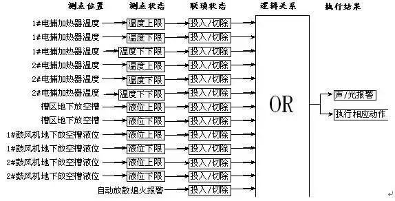
Cold Drum Section Interlock Structure Diagram
Control Effect Analysis
The factors affecting gas collection pipe pressure are diverse, such as coal loading, leveling, pushing coal, and switching machine direction. When these factors are temporarily absent, the coking process system is relatively stable. When the process system is in one or several of the situations such as coal loading, leveling, pushing coal, or switching machine direction, the system will experience a fluctuation period, and the control curve will show a pulse shape. This is because the control system responds rapidly, adjusting its pressure towards the set value. After several adjustments, the system re-enters a stable period, repeating this cycle.
From the control effect diagram, it can be seen that the control effect with frequency conversion is superior to that with the large reflux regulating valve, as the dynamic performance of the motor regulated under the frequency converter is better than that of the regulating valve. However, the latest designed million-ton level cold drum systems have adopted blowers with speed regulation through hydraulic couplings, which are much slower in speed regulation. Moreover, the process does not allow for frequent adjustments. Therefore, involving the large reflux regulating valve in gas collection pipe pressure regulation is currently a reasonable choice. Under the current two control structures, the control deviation range during the stable period is ±20Pa; the fluctuation period’s deviation control range is ±50Pa, but the duration is short enough to meet the process requirements.
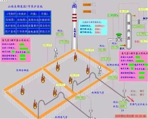
Coke Oven Scene
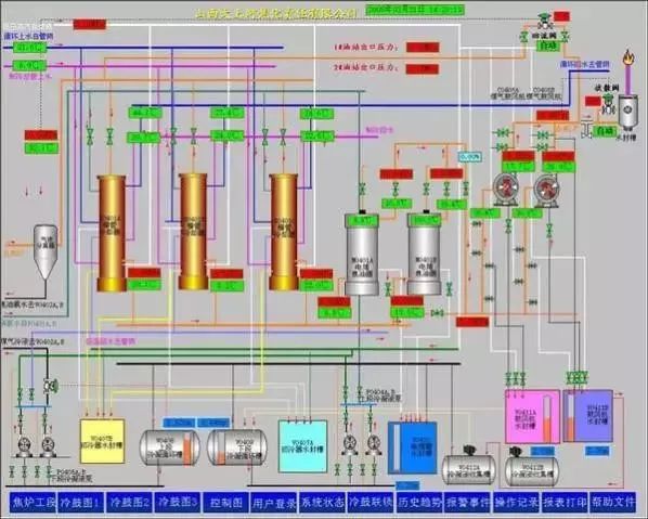
Cold Drum Scene with Low-Pressure Blower 1
Cold Drum Scene with High-Pressure Blower
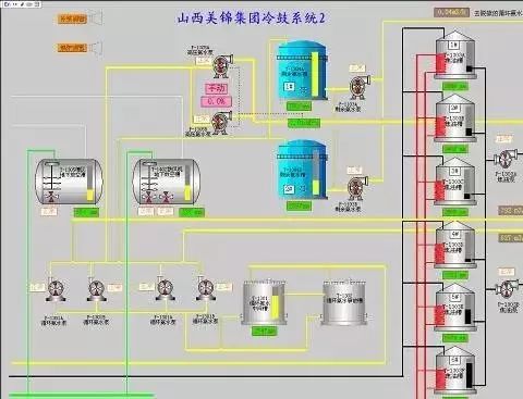 Cold Drum Tank Area Scene
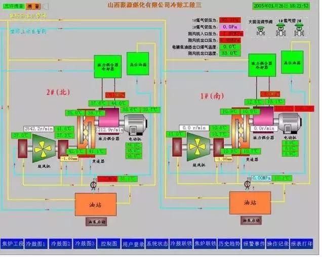 Blower Operation Scene
3Desulfurization, Sulfur Recovery, Ammonium Sulfate and Benzene Washing and De-benzeneProcess Overview
Recovery mainly includes ammonium sulfate, desulfurization and sulfur recovery, and benzene washing and de-benzene sections.
The process flow of ammonium sulfate involves preheating and separating the residual ammonia water to react and generate liquid ammonium sulfate, which is then crystallized, dried, and packaged.
The process flow for desulfurization and sulfur recovery involves the reaction of desulfurization liquid and solution in the desulfurization tower to separate sulfur, after which the solution enters the regeneration tower for regeneration.
The process flow for benzene washing and de-benzene involves the poor and rich oil being cleaned in the benzene washing tower before entering the de-benzene tower, where the difference in temperature produces light benzene oil-water and heavy benzene oil-water, which are then separated using an oil-water separator.
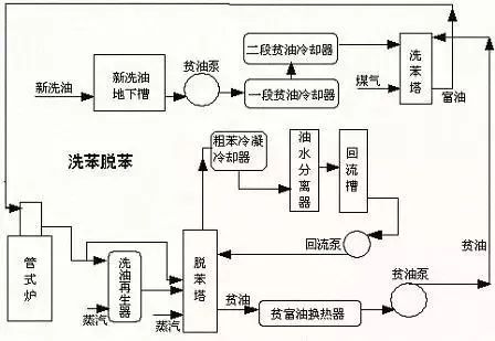 Benzene Washing and De-benzene Process Flow Diagram
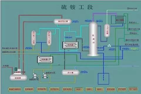 Blower Condensation Section Flow Diagram
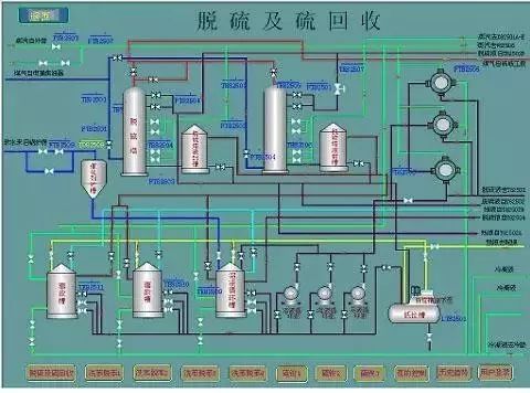 Desulfurization and Sulfur Recovery Process Flow Diagram
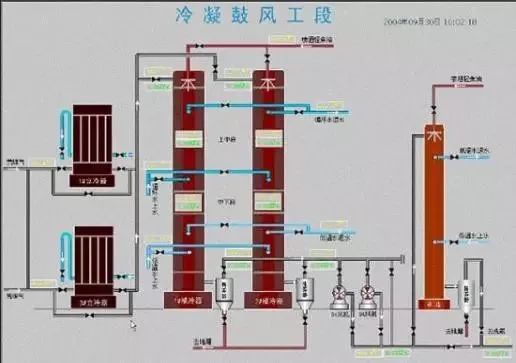 Blower Condensation Section Flow Diagram
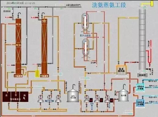 Ammonia Washing and Distillation Section Flow Diagram
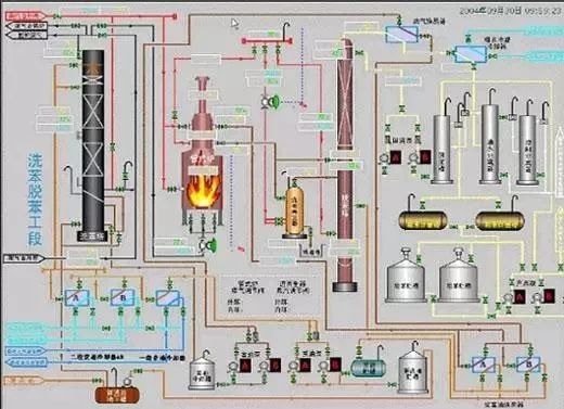 Benzene Washing and De-benzene Section Flow Diagram
Control Scheme
The ammonium sulfate section mainly has two control loops: temperature adjustment of the incoming boiling dryer and temperature adjustment of the steam at the top of the ammonia distillation tower. By detecting the temperature of the incoming boiling dryer and the steam temperature at the top of the ammonia distillation tower and comparing it with the set value, the steam flow entering can be adjusted: conventional PID control can be used.
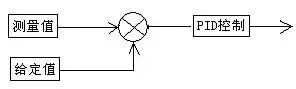
The desulfurization and sulfur recovery section mainly has three control loops: flow adjustment of solution entering desulfurization tower B, flow adjustment of solution entering regeneration tower, and flow adjustment of air entering regeneration tower B, using conventional PID control.
The benzene washing and de-benzene section mainly has two control loops and one interlock control: temperature adjustment of rich oil from the pipe furnace and temperature adjustment of oil vapor at the outlet of the de-benzene tower.
Interlock control is set to cut off the gas to the pipe furnace when the gas pressure is less than 2.0kPa. Once the gas pressure exceeds 2.0kPa, the gas to the pipe furnace is turned back on.
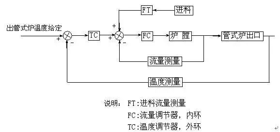
Temperature Cascade Control Diagram of Rich Oil from Pipe Furnace
Here, the inner loop is the cascade control of the superheated steam flow from the pipe furnace to reduce the interference of steam pressure fluctuations.
The temperature adjustment of the oil vapor at the outlet of the de-benzene tower adopts the inner loop of the superheated steam flow from the pipe furnace for cascade control to reduce the interference of steam pressure fluctuations.
In addition, during actual production, the steam pressure may exceed the maximum pressure that the de-benzene tower can withstand. To protect the tower body, a switch is added during cascade control, where if the pressure inside the tower exceeds a certain value, it switches to control based on tower pressure.
4Ammonia DistillationProcess Overview
The ammonia distillation section mainly completes the distillation process of residual ammonia water from the coking blend coal.
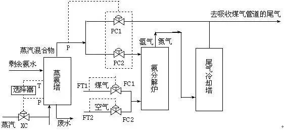 Ammonia Distillation Section Process Flow Diagram
Control Scheme
XC: is the selection control used to control the temperature and pressure of the ammonia distillation tower, with the selection variables being the top temperature T of the ammonia distillation tower and the steam pressure P. Within an appropriate pressure range, temperature adjustment is prioritized; otherwise, it switches to pressure adjustment to ensure the safety of the tower.
PC1 and PC2: are section control adjustments, with the determining variable being the pressure of the mixed gas escaping from the top of the ammonia distillation tower. At pressure interval P1 (low), the mixed gas is sent to the ammonia decomposition furnace; at pressure interval P2 (high), the mixed gas is directly used for tail gas absorption.
FC1 and FC2 control the ratio of air flow to gas flow. In the ammonia decomposition furnace, to ensure the normal operation of the ammonia decomposition process, the appropriate ratio of air flow to gas flow must be maintained to ensure the economic and safe combustion process.
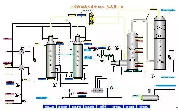 Ammonia Distillation Section Process Flow Diagram
5Crude Benzene RefiningProcess Overview
Crude benzene is a complex mixture composed of various organic compounds, with the main components being benzene and its homologues toluene, xylene, and trimethylbenzene. The crude benzene refining process involves removing unsaturated compounds, sulfides, etc., from crude benzene through chemical methods, followed by distillation to separate benzene products.
In continuous crude benzene refining processes, the five-tower distillation method is commonly used.
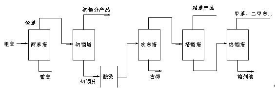 Crude Benzene Refining Process Flow Diagram
Control Scheme
In the crude benzene refining process, the main task is to solve the operational issues of various towers, which share the common goal of material separation. The principle of separation is based on the different relative volatilities of various components in the mixed liquid, allowing the lighter components in the liquid phase to rise and the heavier components to descend, thus achieving the purpose of material separation.
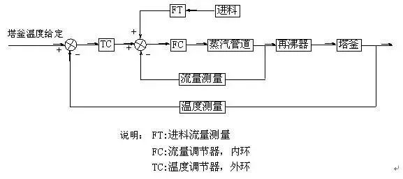 Tower Bottom Temperature Control Diagram
Tower bottom temperature control is achieved by using the flow rate of heating steam and tower bottom temperature for cascade control. The main factor affecting the tower bottom temperature is the heat carried away by the material entering the reboiler, while the heat of the reboiler is provided by the steam entering the tower bottom. Therefore, the tower bottom temperature can be controlled by adjusting the flow rate of steam entering the reboiler, with the feed flow rate introduced for feedforward control to achieve temperature control of the tower bottom. As the addition of steam significantly impacts other parameters such as tower pressure, a condition is added to ensure safety: when the tower pressure is within a safe range, cascade control is applied using steam flow rate and temperature; when the tower pressure is too high, tower pressure control methods are used to reduce tower pressure, ensuring the safety of tower equipment.
Many factors affect the tower top temperature, such as the reflux amount of materials, the amount of heating steam in the reboiler, and the amount of cooling water in the condenser, among which the most significant and strongest influence is the material reflux amount. Therefore, the tower top temperature can be controlled through the reflux amount. However, as the feed amount and its composition are major disturbance factors, and since the five towers are connected in series, the feed from one tower is the input for the next, the feed amount is uncontrollable. Thus, feedforward is introduced here.
Tower Top Temperature Control Diagram
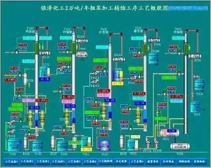 Five-Tower Crude Benzene Refining Flow Chart
6Tar ProcessingProcess Overview
Tar is a liquid product obtained from the dry distillation and gasification process of coal. It is a viscous liquid that is black or dark brown and has a pungent odor. To date, coal tar remains the only source of many polycyclic compounds and heterocyclic compounds containing oxygen, nitrogen, and sulfur. Coal tar products have been widely used in the chemical, pharmaceutical, dye, pesticide, and carbon industries.
The commonly used and mature tar distillation process is the single-tower tar tubular furnace distillation process.
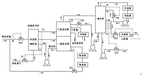 Single-Tower Tar Tubular Furnace Distillation Process Flow Diagram
Control Scheme
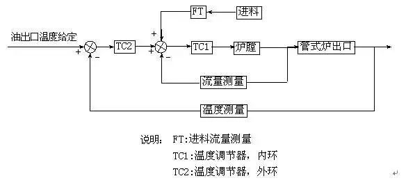 Tubular Furnace Outlet Temperature Control Principle Diagram
Typical Control Links:
FT1: Control of raw tar flow into the tubular furnace.
TT: Tubular furnace tar outlet temperature control: this is the most important control link in the distillation process. Cascade control is used, where T2 is the furnace temperature, serving as the inner loop, reflecting rapid changes in furnace temperature, and T1 is the tubular furnace outlet temperature, serving as the inner loop, with slower variations for fine-tuning. Ideally, the control error should be within 1 to 2°C, fully meeting process control requirements.
TT3: Temperature adjustment at the top of the second-stage evaporator tower, controlling the tower top components, single loop.
TT4: Temperature adjustment at the top of the fractionation tower, controlling the tower top components, single loop.
LT1: Level adjustment of liquid at the bottom of the first-stage evaporator tower, controlling the tower bottom level. Due to the long travel of materials in the process pipeline, there is a significant delay in control, but it can still be maintained within an appropriate range, single loop.
LT2: Level adjustment of liquid at the bottom of the fractionation tower, controlling the tower bottom level. In automatic mode, a lower limit for level control should be set to prevent the control valve from clogging, single loop.
FT2: Control of three mixed oil flow, single loop.
7Industrial Naphthalene
Naphthalene is an important raw material in the organic chemical industry, primarily found in coal tar. The wide fraction containing naphthalene cut from tar processing can be further refined to obtain industrial naphthalene with 95% naphthalene content.
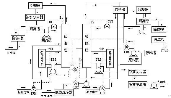 Dual Furnace Dual Tower Industrial Naphthalene Production Control Process
Typical Control Links:
TRB, TRR: Control of gas flow into the initial distillation tubular furnace and the refining tubular furnace, aimed at controlling the material outlet temperature of the tubular furnace while stabilizing the tower bottom temperature. This link uses cascade control, with furnace temperature as the inner loop and material outlet temperature as the outer loop.
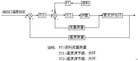 Tubular Furnace Outlet Temperature Control Principle Diagram
TU1, TU2: respectively, the temperature adjustment at the top of the initial distillation tower and the refining tower, adjusting the top temperature through the reflux amount at the top, with appropriate top and bottom temperatures facilitating the smooth mass and heat transfer process within the tower.
LR1, LR2: respectively, the low level adjustment of the initial distillation tower and the refining tower bottom level adjustment, preventing the tower bottom level from being too high and flooding the tower or too low, interrupting the distillation process.
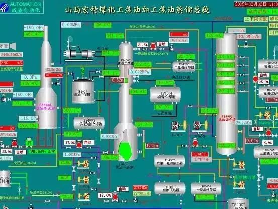
Tar Distillation Main Control Screen
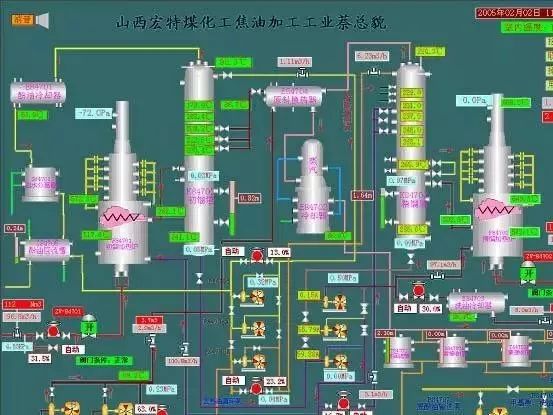 Industrial Naphthalene Main Control Screen
Control Effect Analysis
The core control in the tar processing process is the control of the tubular furnace outlet temperature. Through our DCS adjustment, the deviation of this outlet material temperature can be controlled within ±1 to 2°C, fully meeting production process requirements. From the trend chart, it can be seen that other related processes also operate smoothly.
Source: Tianhua Cloud
This issue edited by: Liu Xiaonan