Advertisement Divider
PCB Network City News

Professor Bai Rongsheng is well-known in the industry and has been writing articles related to circuit boards and their upstream and downstream since 1988. He has published more than ten professional books including “The Complete Book on PCB Wet Processes”, “PCB and Lead-Free Soldering”, “PCB Terminology Handbook”, “PCB Terminology Handbook – Basic Edition”, and “PCB Micro-Slicing Handbook”. He has many years of rich experience in failure analysis of electronic components and analyzes the causes and countermeasures of failures based on actual cases to improve product reliability.
Moreover, Professor Bai has unique insights into the technology fields of the PCB industry’s upstream and downstream supply chains. For decades, he has been personally involved in research and writing without any slack.
PCB Network City has been sharing Professor Bai’s expert technical articles published in “Printed Circuit Information” to help colleagues in the industry.
This article is from the “Expert Forum” section of “Printed Circuit Information” (November 2023 issue, “5G Circuit Board and Carrier Board Failure Analysis Part Two”). Unauthorized reproduction by any individual or organization is prohibited. For reprinting, please contact us for permission. Thank you!
Previous Link:Expert Forum | Bai Rongsheng: The Strong Demand for 5G PCB is Unprecedented (7) – 5G Circuit Board and Carrier Board Failure Analysis Part OneExpert Forum | Bai Rongsheng: The Strong Demand for 5G PCB is Unprecedented (7) – 5G Circuit Board and Carrier Board Failure Analysis Part One
Expert Forum | Bai Rongsheng: 5G Circuit Board and Carrier Board Failure Analysis Part Two
5G has been around for two years, and the demand for thick cloud PCBs and thick carriers exceeds that for thin boards used in terminal smartphones and computers. The failure issues occurring during mass production of both are not entirely the same. This issue compiles 280 frames of color illustrations for readers.
Continuing from the last issue
5.6 Over-expansion and excessive resin removal causing copper diffusion CAF
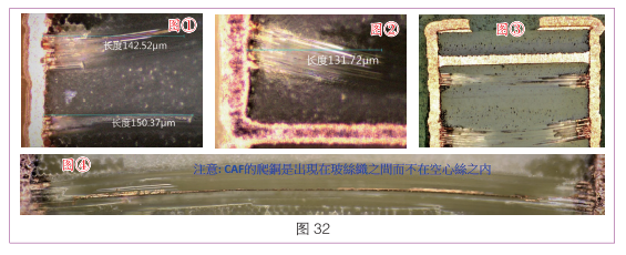
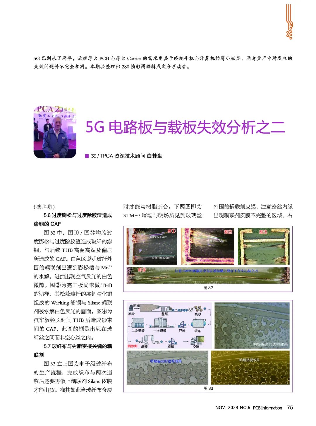
In Figure 32, both Figure ① and Figure ② show copper diffusion caused by over-expansion and excessive resin removal, along with subsequent THB high temperature, high humidity, and bias-caused CAF. The white area indicates that the coupling agent around the glass fiber has been hydrolyzed by the expansion groove and Mn+7, resulting in air-reflective white micro-gaps. Figure ③ shows an unfinished board that has not yet undergone THB cutting, with loose glass fibers showing diffusion of palladium and copper forming wicking diffusion and silane coupling agents hydrolyzed to reveal white reflective surfaces. Figure ④ shows the CAF caused by long-term THB on automotive boards, where copper appears between glass fibers rather than within hollow fibers.
5.7 Key coupling agents for the close contact between glass fiber cloth and resin
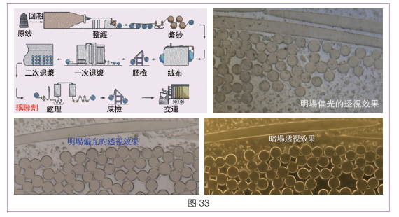
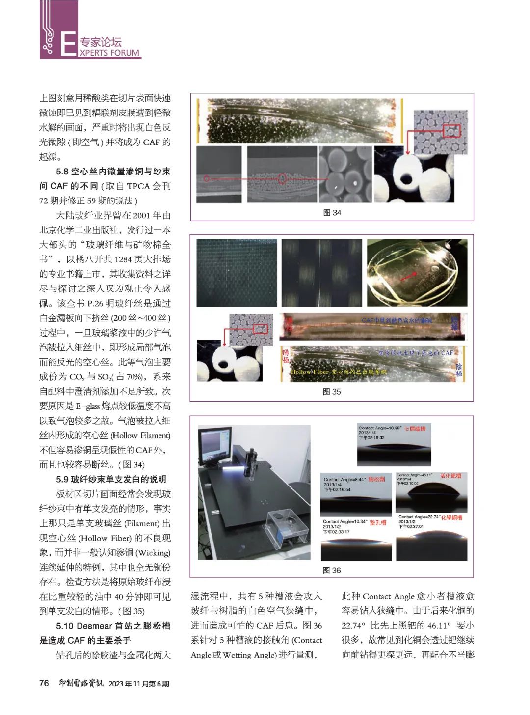
Figure 33 shows the production process of electronic-grade glass fiber cloth. After completing weaving and two rounds of desizing, a silane coupling agent film must be applied before shipment. Only then can the glass fiber cloth bond with the resin during impregnation. The lower two images show the coupling agent film around the glass fibers seen in STM-7 dark field and bright field. Note the incomplete areas of the coupling agent film at the inner edge of the dense fibers. The upper right image deliberately uses dilute acid to quickly etch the surface of the slice, revealing a slight hydrolysis of the coupling agent film, which, if severe, will show white reflective micro-gaps (i.e., air) and become the source of CAF.
5.8 Differences between micro copper diffusion within hollow fibers and CAF between fiber bundles (from TPCA Journal Issue 72 and corrected from Issue 59)
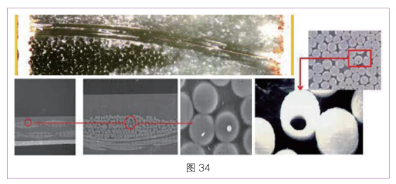
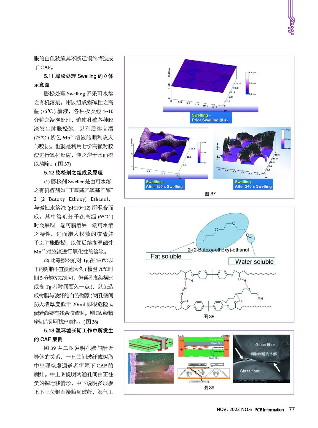
The mainland glass fiber industry published a large volume book titled “Glass Fibers and Mineral Wool Complete Book” in 2001 through the Beijing Chemical Industry Press, consisting of 1284 pages in octavo format, showcasing its comprehensive data collection and in-depth discussions. On page 26, it states that glass fibers are extruded downward through a platinum leak plate (200-400 filaments). If a few bubbles from the glass slurry are drawn into the fine fibers, they form localized bubbles that can reflect light, resulting in hollow fibers. These bubbles primarily consist of CO2 and SO2 (accounting for 70%), caused by insufficient clarifying agent in the formulation. A secondary reason is that the lower melting point of E-glass leads to more bubbles. The hollow fibers formed by bubbles drawn into the fine fibers not only easily diffuse copper, presenting false CAF but are also more prone to breakage (Figure 34).
5.9 Explanation of single fiber bundles appearing white
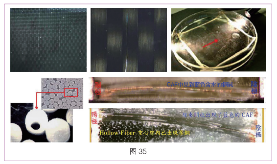
In the slice images of the board area, it is often found that single fibers in the fiber bundle appear shiny. In fact, this is merely a single glass fiber (Filament) exhibiting the poor phenomenon of hollow fibers (Hollow Fiber), rather than a typical case of copper diffusion (Wicking) extending continuously, with no copper present. The inspection method is to immerse the original glass fiber cloth in lighter oil for 40 minutes to observe the appearance of single fibers turning white (Figure 35).
5.10 The swelling groove at the initial desmear stage is a major killer of CAF
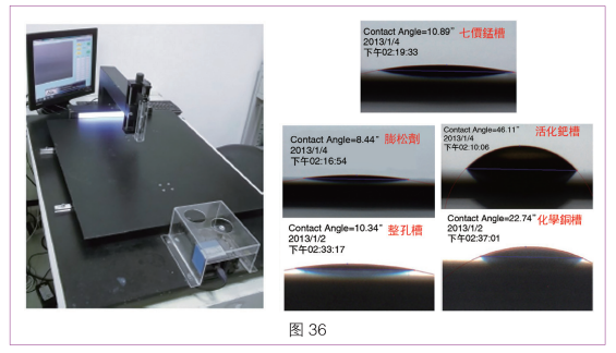
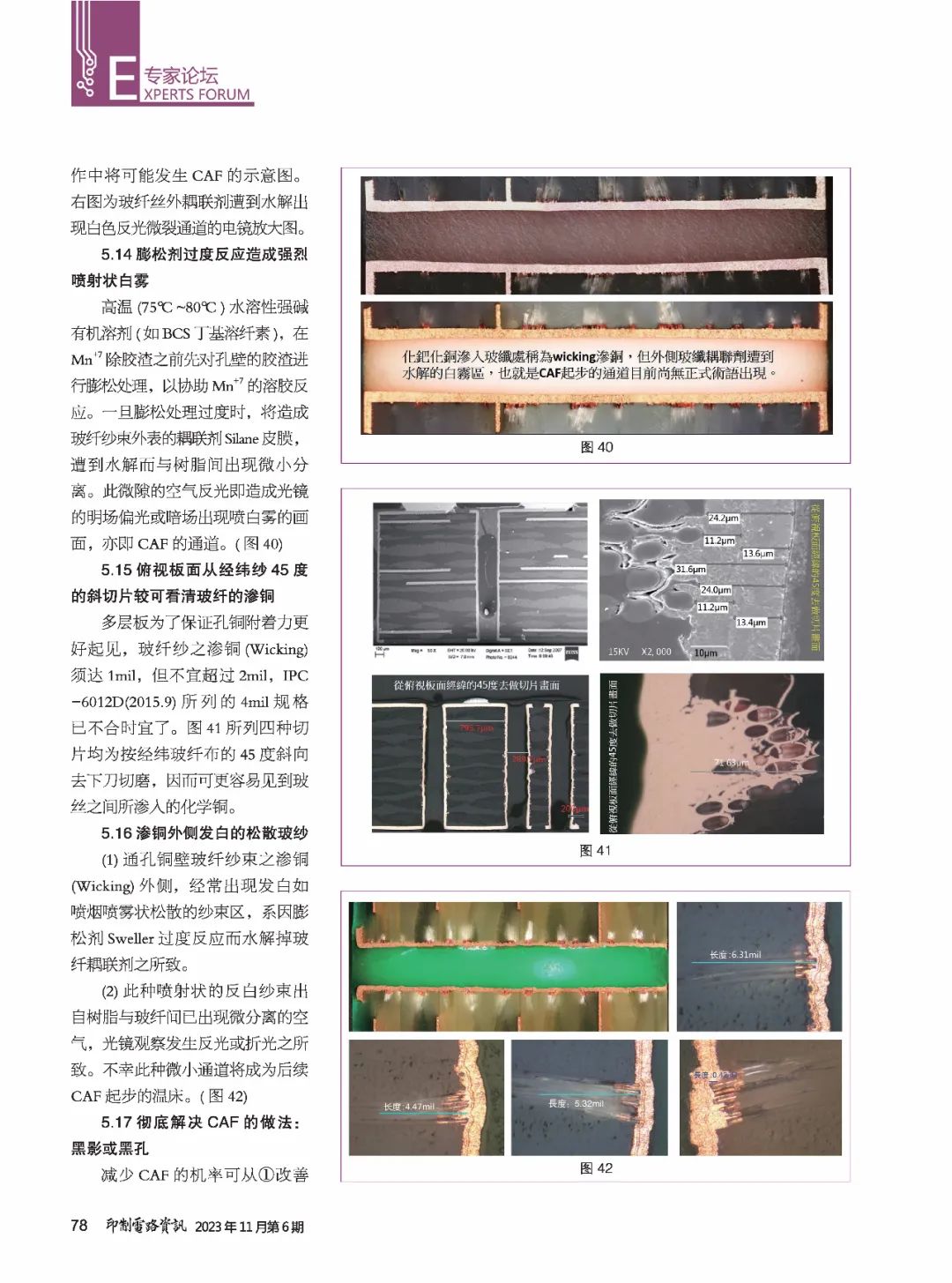
In the two wet processes of drilling and metallization, five types of groove liquids can invade the white air gaps between glass fibers and resin, leading to dreadful CAF consequences. Figure 36 measures the contact angles (Contact Angle or Wetting Angle) of these five groove liquids. The smaller the contact angle, the easier the groove liquid penetrates the gap. Since the contact angle of the subsequent copper plating at 22.74° is much smaller than that of the black palladium at 46.11°, it is common to see copper plating continuing to drill deeper through palladium, combined with improperly expanded white gaps, leading to continuous copper migration and ultimately causing CAF.
5.11 Three-dimensional illustration of swelling treatment
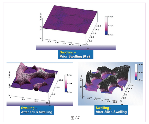
The swelling treatment involves using a water-soluble organic solvent to create a strongly alkaline high-temperature (75°C) groove liquid. Various boards are immersed for 1 to 10 minutes, forcing the walls of the holes to swell and relax, facilitating the subsequent high-temperature (75°C) purple Mn+7 groove liquid to penetrate and etch. This utilizes heptavalent manganese to oxidize the resin residues, allowing them to dissolve in water for removal (Figure 37).
5.12 Composition and principle of the swelling agent
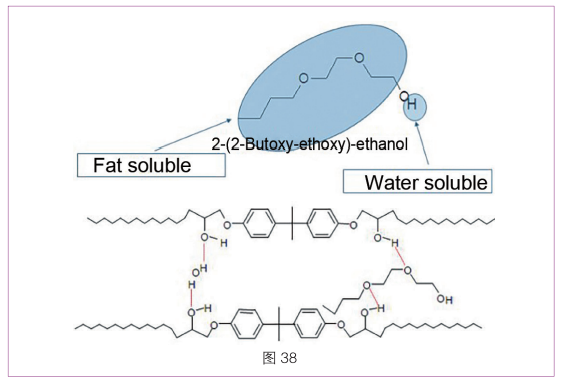
(1) The swelling agent Sweller is made from water-soluble organic solvents like “Butoxyethoxyethanol” 2-(2-Butoxy-Ethoxy)-Ethanol, mixed with alkaline aqueous solutions (pH 10-12). The solvent molecules exhibit one end being lipophilic and the other hydrophilic at high temperatures (65°C), allowing them to penetrate loose resin residues and cause swelling for subsequent high-temperature alkaline Mn+7 to oxidize and dissolve the residues.
(2) Such swelling agents should not be immersed for too long in resins with Tg below 150°C (around 5 minutes at 70°C), especially for high aspect ratio through holes or high Tg boards, which may require longer immersion to avoid causing white micro-gaps between the resin and glass fiber (a thickness below 20 mil is very dangerous). If residual resin is still suspected, FA-grade precision slicing can reveal the truth (Figure 38).
5.13 CAF cases arising from long-term operation in wet environments
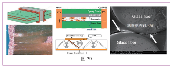
Figure 39 shows the relationship between the hole wall and nearby conductors. Once a void appears in the glass fiber or resin between them, it will lay the groundwork for CAF. The middle upper image illustrates the copper migration from positive to negative between two through holes, while the middle lower image shows the contact of positive and negative copper surfaces with glass fibers in multilayer boards, indicating the potential for CAF during wet operation. The right image is an electron microscope enlargement showing the hydrolyzed coupling agent of glass fibers, resulting in white reflective micro-crack channels.
5.14 Overreaction of the swelling agent causing intense mist-like white spray
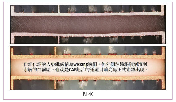
High-temperature (75°C-80°C) water-soluble strong alkaline organic solvents (like BCS butyl cellulose) are used to swell the resin residues on the hole walls before the Mn+7 treatment. If the swelling treatment is excessive, it will cause the coupling agent silane film on the outer surface of the glass fiber bundles to hydrolyze, resulting in small separations between the resin and fiber. This micro-gap’s air reflection causes the bright field or dark field of the optical microscope to show a white mist, which is the CAF channel (Figure 40).
5.15 A better view of copper diffusion in glass fibers when viewed from a 45-degree angle
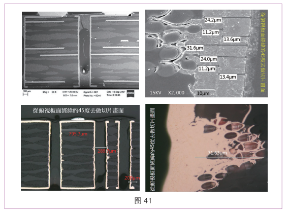
To ensure better adhesion of copper to the hole walls in multilayer boards, the copper diffusion (Wicking) in glass fiber bundles must reach 1 mil but should not exceed 2 mil. The 4 mil specification listed in IPC-6012D (2015.9) is now outdated. The four slicing images in Figure 41 are all made by cutting at a 45-degree angle to the warp and weft glass fiber cloth, making it easier to see the chemical copper diffused between the glass fibers.
5.16 Loose glass fibers showing white diffusion on the outside
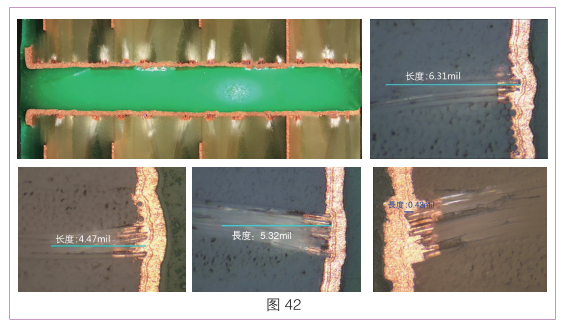
(1) The copper diffusion (Wicking) outside the glass fiber bundles in through holes often appears white and spray-like due to the excessive reaction of the swelling agent Sweller, which hydrolyzes the glass fiber coupling agent.
(2) This spray-like white fiber results from air appearing between the resin and glass fiber, causing reflection or refraction during optical observation. Unfortunately, this small channel will become a breeding ground for subsequent CAF (Figure 42).
5.17 Thorough solutions to CAF: Black shadows or black holes
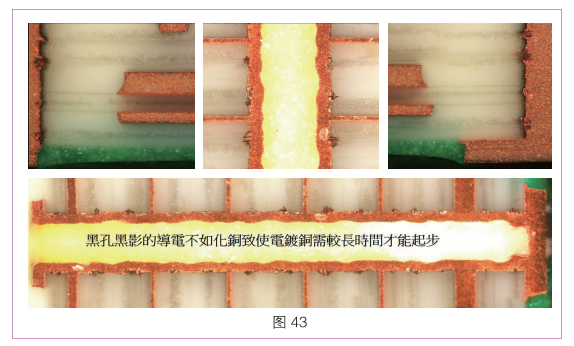
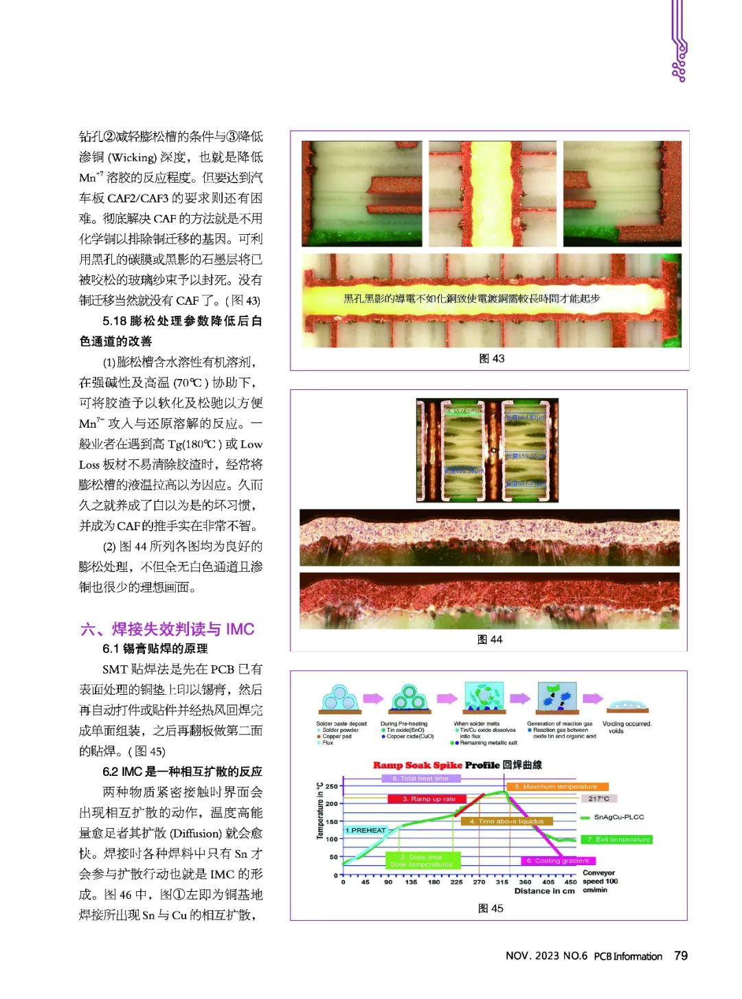
The probability of CAF can be reduced by (1) improving drilling, (2) lightening the conditions of the swelling groove, and (3) reducing copper diffusion (Wicking) depth, which means lowering the reaction degree of Mn+7 solution. However, meeting the CAF2/CAF3 requirements for automotive boards remains challenging. The thorough solution to CAF is to eliminate the genetic cause of copper migration by not using chemical copper. The use of carbon films or graphite layers to seal the loosened glass fiber bundles will prevent copper migration and thus eliminate CAF (Figure 43).
5.18 Improvement of white channels after reducing swelling treatment parameters
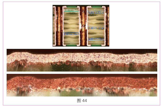
(1) The swelling groove contains water-soluble organic solvents, which, under strong alkalinity and high temperatures (70°C), assist in softening and relaxing resin residues to facilitate the reaction of Mn+7 penetration and reduction. Generally, when encountering high Tg (180°C) or Low Loss boards that are difficult to clean, operators often raise the temperature of the swelling groove liquid, mistakenly believing it is a solution. Over time, this leads to a bad habit that becomes a promoter of CAF, which is very unwise.
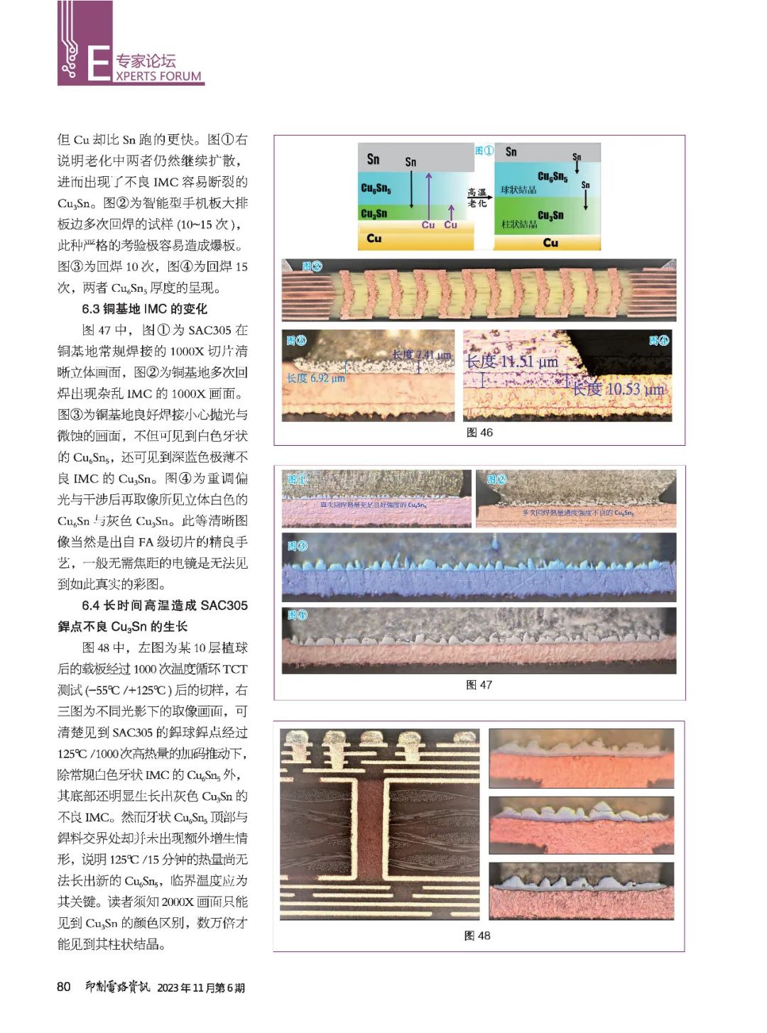
(2) The images in Figure 44 all show good swelling treatment results, with no white channels and minimal copper diffusion.
For more content, scroll down to view the imagesand
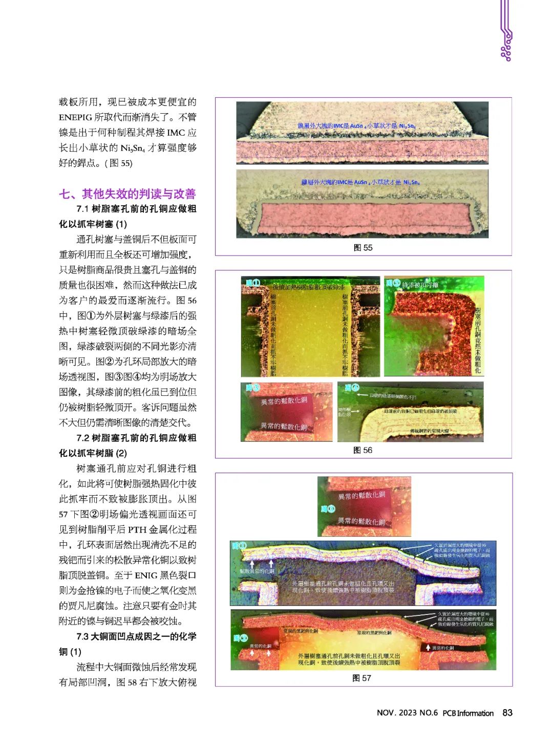
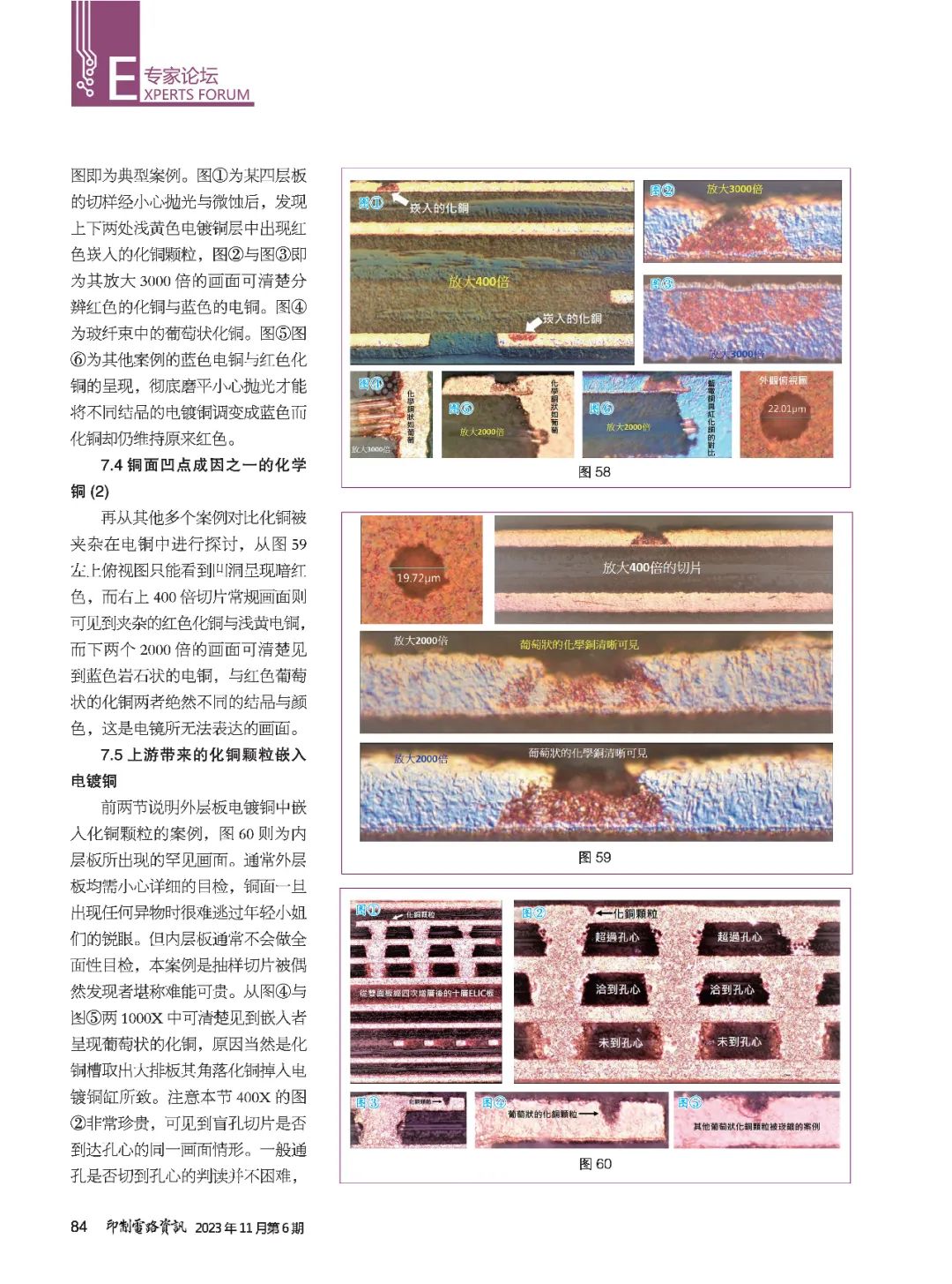
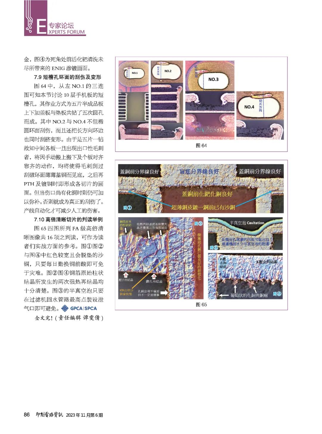
This article is from the November 2023 issue of “Printed Circuit Information”. The e-book is now online. Readers can scan the QR code below or click “Read the Original” at the end of the article for more exciting content. ▲ “Printed Circuit Information” Electronic Edition▲