Skip to content
Click↑↑Technical Training, follow and pinto subscribe for free long-term
200,000+Industrial control professionals follow our WeChat platform: technical sharing, learning exchange, industrial control videos
The HMI of the THPSSM-1 system uses the Siemens SMART 700 touch screen. The HMI serves as a bridge for two-way communication between the operator and the machine, allowing users to freely combine text, buttons, graphics, numbers, etc., to process, monitor, and manage information that may change at any time on a multifunctional display screen.
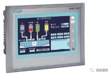
1. Please ensure sufficient space is reserved for all connecting cables outside the HMI device.
2. When installing the HMI device, ensure that personnel, workbenches, and the overall equipment are properly grounded.
3. Power connection: only DC24V.
Smart 700 panel description:
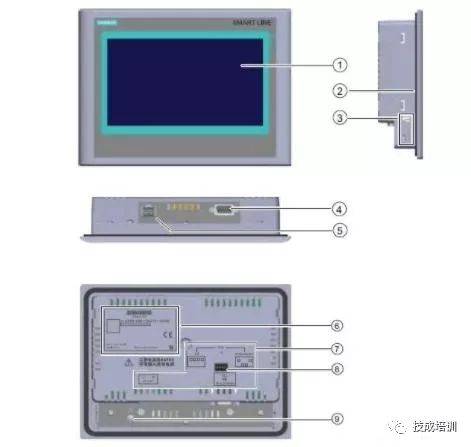
① Display/Touch Screen, ② Installation Sealing Pad, ③ Installation Slot for Card Peg;
④ RS422/RS485 Interface, ⑤ Power Connector, ⑥ Nameplate;
⑦ Interface Name, ⑧ DIP Switch, ⑨ Functional Ground Connection.
1. Connecting Configuration PC
1. The configuration PC can provide the following functions:
1.2 Transfer device images;
1.3 Restore the HMI device to factory default settings;
1.4 Backup and restore project data.
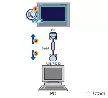
2. Connect the configuration PC with the Smart Panel:
2.1 Turn off the HMI device;
2.2 Connect the RS485 connector of the PC/PPI cable to the HMI device;
2.3 Connect the RS232 connector of the PC/PPI cable to the configuration PC.
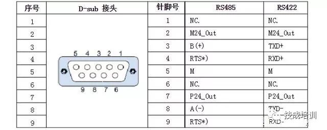
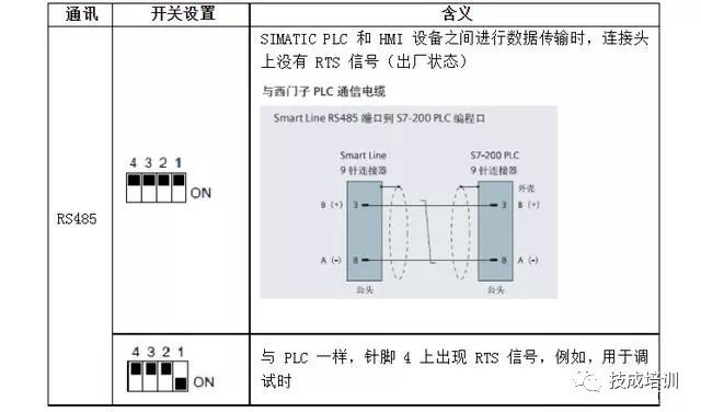
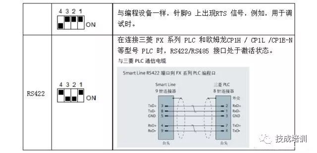
2. The table below shows the DIP switch settings. The RTS signal can be used for internal switching of the send and receive directions.
1. The user must enable the data channel to transfer the project to the HMI device.
2. Note: After completing the project transfer, the HMI device can be protected by locking all data channels to prevent accidental overwriting of project data and HMI device images.
3. Enable a data channel – Smart Panel (Smart 700)
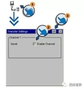
3.1 Press the “Transfer” button to open the “Transfer Settings” dialog.
3.2 If the HMI device is interconnected with the configuration PC via the PC-PPI cable, activate the “Enable Channel” checkbox in the “Channel 1” field.
3.3 Use “OK” to close the dialog and save the input.
4. Installation of WinCC flexible 2008 Software
1. First install WinCC flexible 2008 CN
2. Next install WinCC flexible 2008_SP2
3. Finally install Smart panel HSP
Follow the wizard prompts, keep pressing [Next], and then press [Finish] to complete the software installation.
5. Create a Simple Project
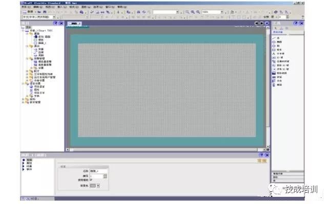
1. After installing WinCC flexible 2008 software, find the corresponding executable program under [Start]/[Programs]/[WinCC flexible 2008] and click to open the touch screen software. The interface is as follows:
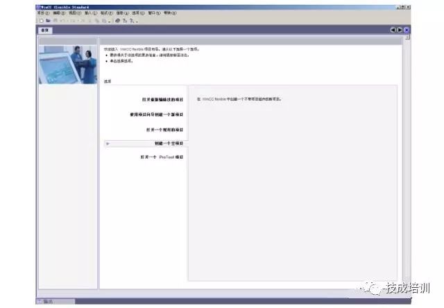
2. Click on the [Create an Empty Project] in the [Options] menu, select the touch screen [Smart Line][Smart 700] in the pop-up interface, click OK, and enter the following interface.
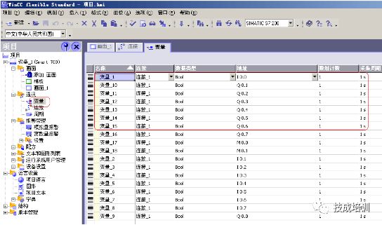
3. In the above interface, double-click on “Connections” under the left menu, select the communication driver (SIMATIC S7 200). After setting, double-click on “Variables” under the left menu to create a variable table. As shown in the figure below:
4. After establishing the variables, double-click on “Add Screen” under the left menu to increase the number of screens, then select Screen 1 to create screen functions, such as creating a button to return to the initial screen. Select “Button” on the right, set the text display under “General,” set the function under “Events” to “Click” as shown in the figure, and set other appearance displays under “Appearance” to complete the return function button settings.

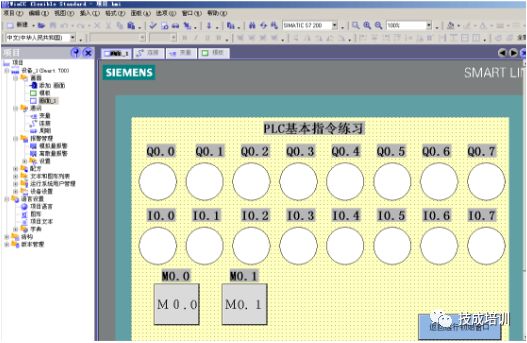
5. Create an indicator light to monitor the status of the PLC input and output ports. Select “Circle” on the right and set it as follows under “Appearance”:

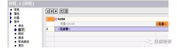
6. Create a button to control the PLC program. Select “Button” on the right, set the “Set Button” under “Events” as shown in the figure below:
7. A simple screen has been created as shown below:
1. Connect the touch screen PPI/RS422/RS485 interface to the PC serial port via the PC/PPI communication cable.
2. The touch screen must enable the data channel and select “Control Panel.” In the pop-up window, activate the “Enable Channel” checkbox, then close it. After that, select “Transfer” to start the download.
3. Click the download button to download the project. As shown in the figure below:

4. After the download is complete, the touch screen must enable the data channel and select “Control Panel.” In the pop-up window, uncheck the box and close it. Connect the PLC and touch screen using a dedicated connection cable to achieve the set control.
Source: Internet, copyright belongs to the original author, infringement will be deleted
Remember to click “Read More“
Click↓Read the original text,morefree learning on electricians and PLC knowledge