
Analog Signal refers to information represented by continuously varying physical quantities, such as temperature, humidity, current, voltage, etc. Its value changes continuously and can take an infinite number of different values within a certain time range.
Digital Signal has discrete, non-continuous values and is commonly represented by 1 and 0 in binary.
In digital circuits, logic gates are the basic units of digital circuits, and many complex digital circuits are composed of these basic units. The most basic logic gates areAND Gate, OR Gate, and NOT Gate. These three basic logic gates can be combined to formNAND Gate, NOR Gate, XOR Gate, and XNOR Gate. Logic gates are circuits where the input and output can only have two states: either 0 or 1, typically defined as 1 for high level and 0 for low level. Logic gates are logical circuits that dictate that a signal will only output when the input signal meets a certain logical relationship. Let’s take a look at the characteristics of these logic gates together!01AND GateThe AND gate can achieve the “AND” logical relationship. The AND gate has two or more input terminals and one output terminal. The logic symbol for the AND gate is shown in the figure below (a).
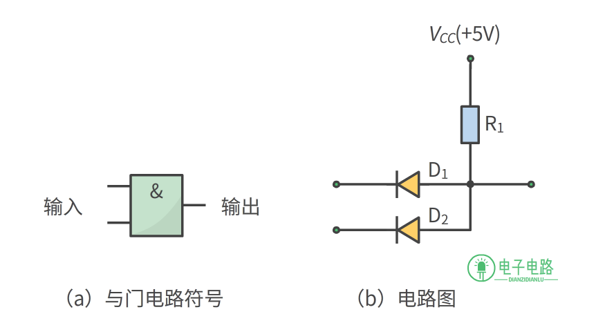
The AND gate can be implemented by the diode and resistor circuit shown in the figure above (b). The output Y will output 1 only when all input terminals are 1 (high level); otherwise, the output Y will output 0.
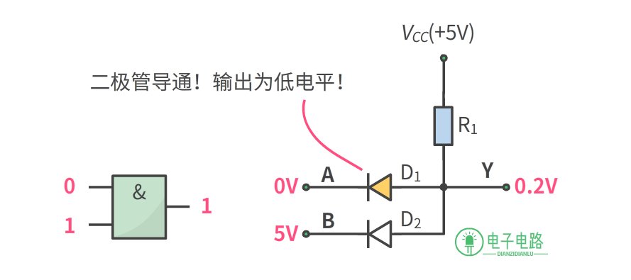
For example, in the figure above, when the AND gate circuit inputs 0 and 1, assuming the power supply voltage is +5V, then 5V is high level, and 0V is low level. As long as any one of the diodes conducts, the output terminal Y will be clamped to 0.2V (low level).
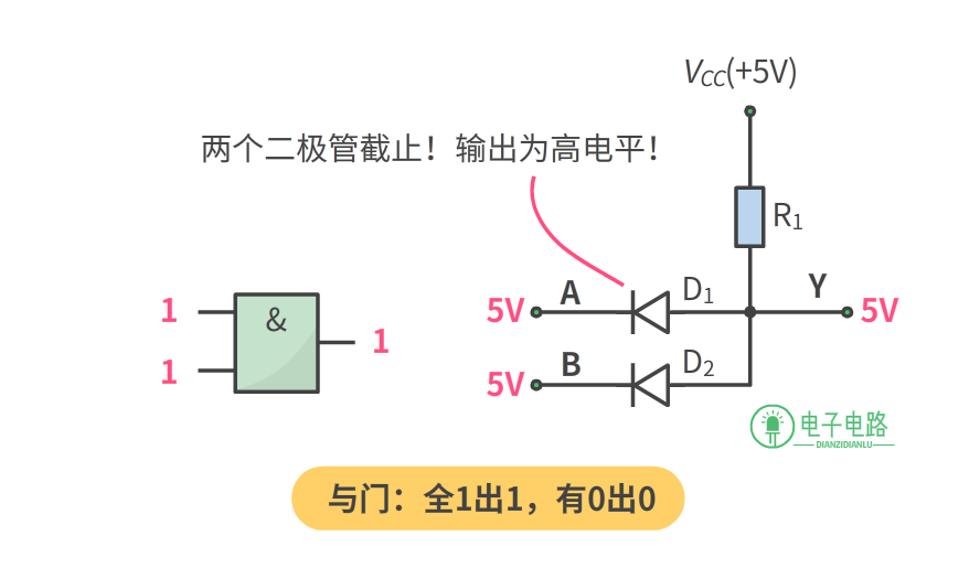
Only when both diodes are cut off will the output Y output 5V (high level); this is the AND gate. The mathematical expression for the AND gate can be represented as:AND Gate Logic Expression: Y=AB We can list the possible input and output values using a table (truth table):
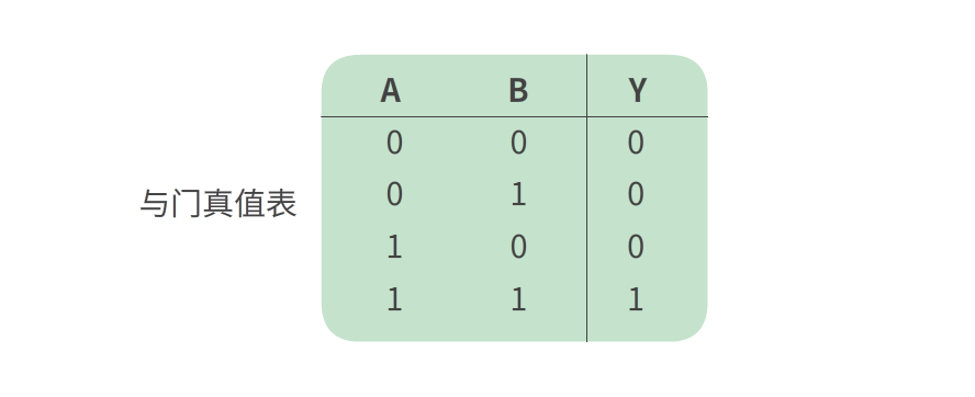
Truth Table is used to represent all possible states between inputs and outputs. It is often used in the analysis process of digital circuits. The truth table shows all possible values for inputs and outputs.
02OR Gate
The OR gate can achieve the “OR” logical relationship, and the logic symbol for the OR gate is shown in the figure below (a).
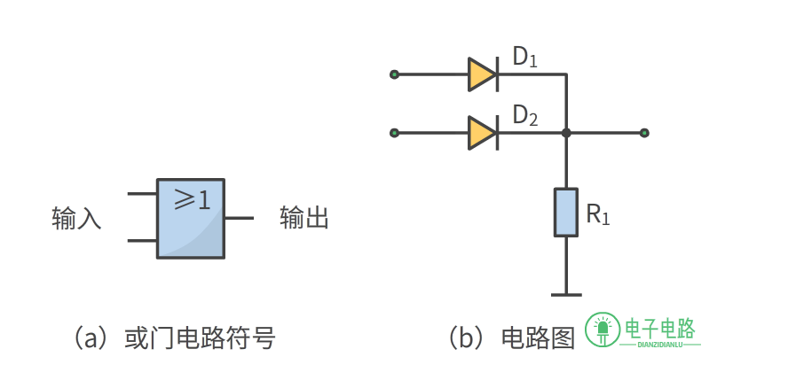
The OR gate circuit can be implemented by the circuit shown in the figure above (b). As long as one of the input terminals is 1 (high level), the output Y will output 1; when all input terminals are 0, the output Y outputs 0.
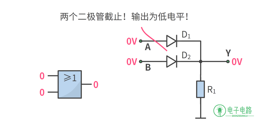
For example, in the figure above, when the input is low level (0V), both diodes are cut off, and the output is low level.
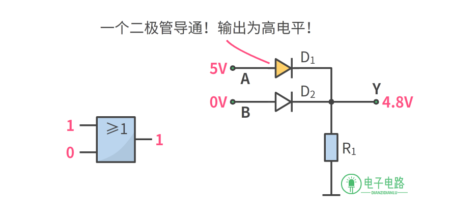
When any one of the input terminals is high level (1), one of the diodes will conduct, and the output Y will be clamped to high level (4.8V). This is the OR gate, and the mathematical expression for the OR gate can be represented as:
OR Gate Logic Expression: Y=A+B
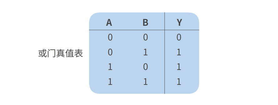
The truth table for the OR gate circuit is as follows:
03NOT Gate
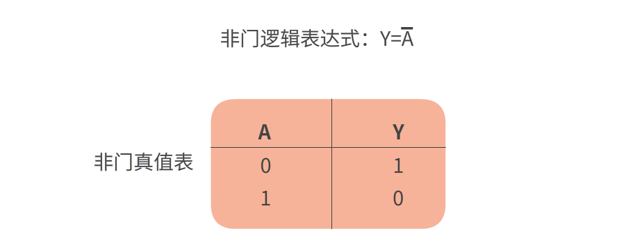
The NOT gate can achieve the “NOT” logical relationship, and the NOT gate has only one input terminal and one output terminal. The logic symbol for the NOT gate is shown in the figure below (a).
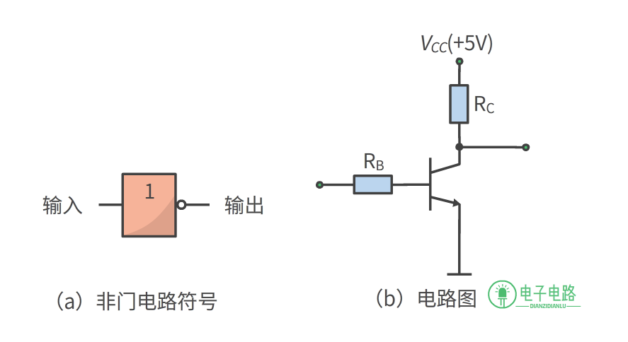
The NOT gate circuit can be implemented by the transistor circuit shown in the figure above (b). When the NOT gate circuit inputs high level (1), the output will be low level (0).
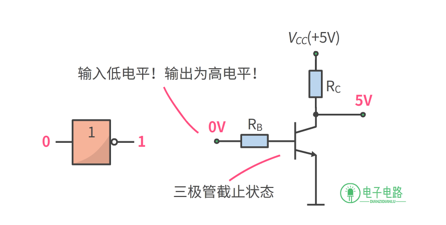
As shown in the figure above, the transistor in the figure is an NPN transistor. When the input terminal inputs 0V (low level), the transistor enters cutoff state, and the output terminal outputs 5V (high level).
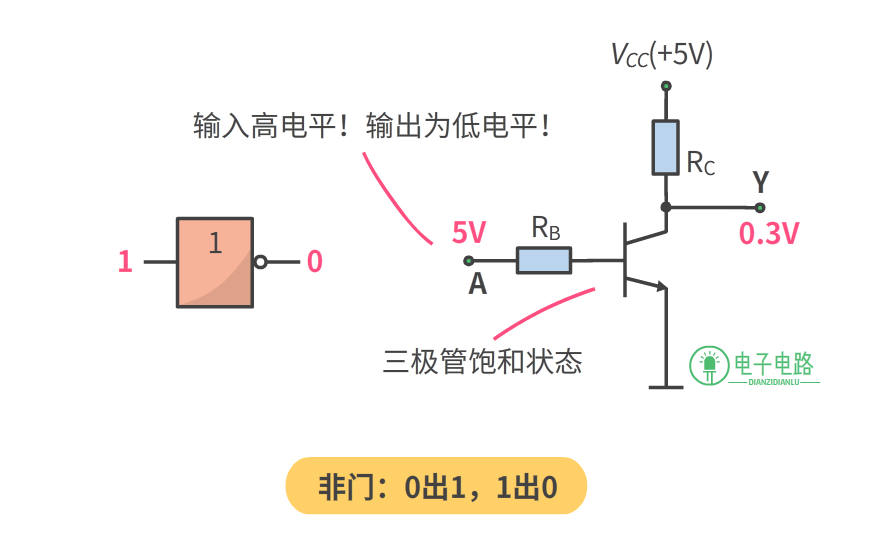
When the input terminal inputs 5V (high level), the transistor will enter saturation state, and the voltage drop between the collector and emitter is very small, just like the switch is closed, so the output Y is low level.
04NAND Gate, NOR Gate, XNOR Gate, XOR GateThe above article discusses the three basic types of logic gates. When these three types of gates are combined, they can form other gates such as NAND, NOR, XNOR, and XOR gates.
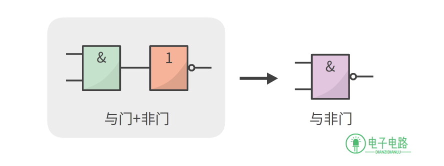
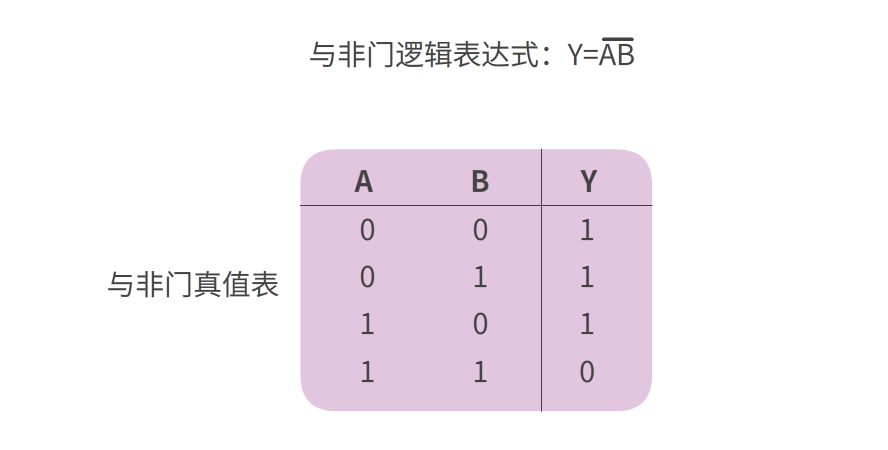
As shown in the figure below, when an AND gate and a NOT gate are combined, it becomesNAND Gate.
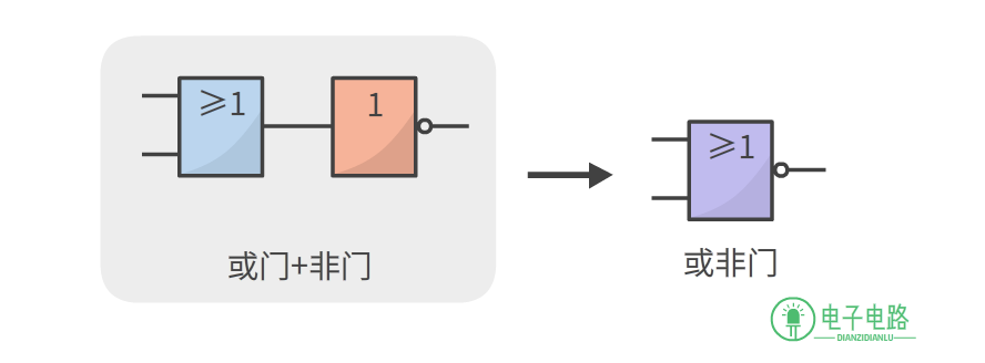
As shown in the figure below, when an OR gate and a NOT gate are combined, it becomesNOR Gate.
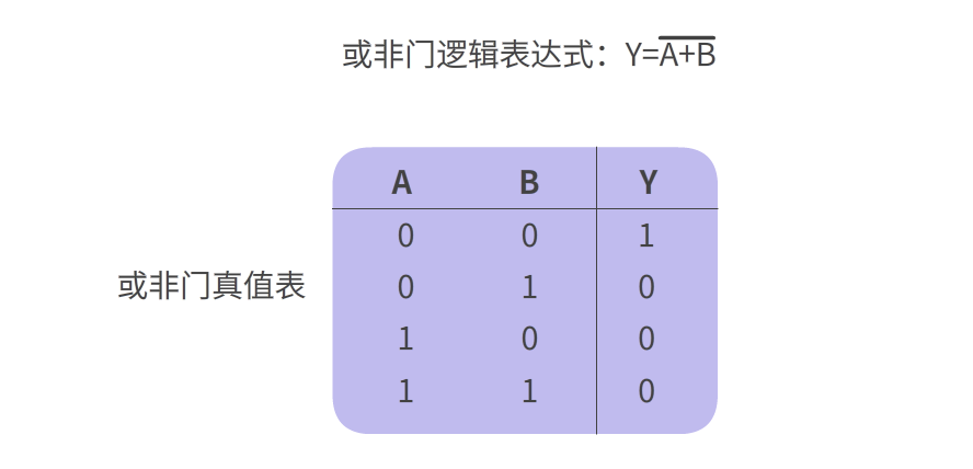
When four NAND gates are combined, they can form anXOR Gate circuit, as shown in the figure below.
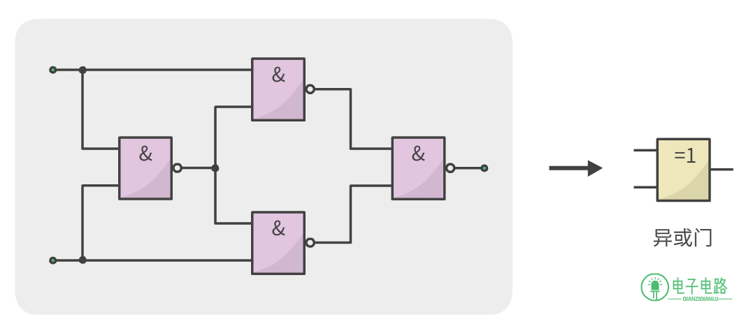
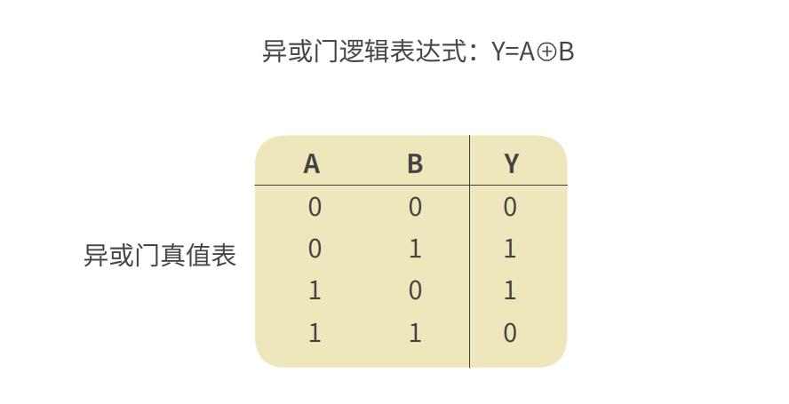
The characteristics of the XOR gate are: same as 0, different as 1. This means that when both inputs are 0 or both are 1, the output is 0; when one input is 0 and the other is 1, the output is 1.
When three NAND gates and one AND gate are combined, they can form aXNOR Gate circuit, as shown in the figure below.
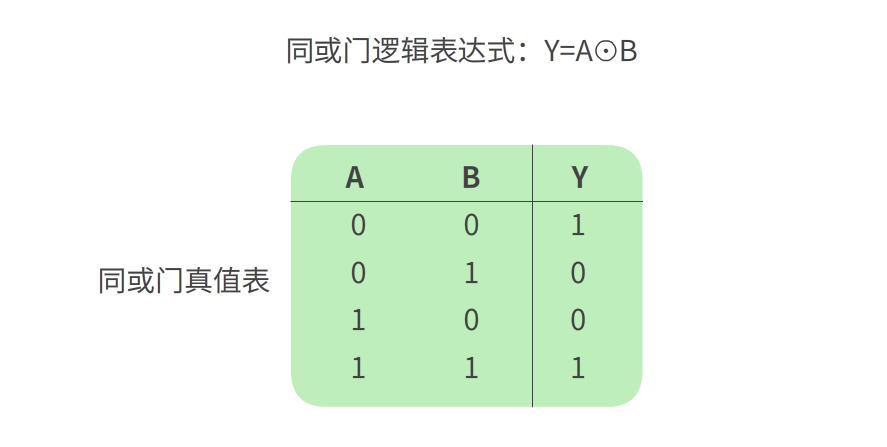
The characteristics of the XNOR gate are: same as 1, different as 0. This means that when both inputs are 0 or both are 1, the output is 1; if one input is 0 and the other is 1, then the output is 0.
Surprisingly, just by combining three AND, OR, and NOT gates, we can create so many variations! Of course, besides these circuits, other combinational logic circuits can also be formed through combinations.
Author: Electronic Circuit
This article is reproduced from Electronic Circuit, and Electronic Engineering Magazine maintains neutrality regarding the views expressed in the article, which are for learning and communication purposes only.
 END▼Previous Hot Articles Review▼Apple’s “Interface Abacus”: Standards and InterestsIs the “Dual Core” on Vivo Phones Really Valuable?South Korea’s Semiconductor Industry: The Dilemma of the “Little Follower”Do Analog Circuit Designers Still Have a Presence?Review Activity

Jiangbolong FORESEE XP2100 PCIe 4.0 X4 NVME SSD 1TB
Review Task:
1. From the date of receiving the product, you must complete (choose one of the following two options) by the specified date:
(1) 1 graphic review
(2) 3-5 minute video introduction
2. The review will be published in the Breadboard Community. The title of the review work should follow the format 【Jiangbolong FORESEE XP2100】+ self-made title
3. Please strictly submit the review report according to the “Review Plan” submitted during application. Simple unboxing, powering on, and other simple review reports are prohibited.
Reward:
After completing the review, Jiangbolong will give a 256GB mobile hard drive

Scan to apply for free

 Share
Share Bookmark
 Like
Like View
View