Based onDr. Miro Samek‘s Modern Embedded Systems Programming Course Content of Section 22, this article summarizes the key points — the concept of Real-Time Operating Systems (RTOS). Here, RTOS specifically refers to the real-time kernel (Real-Time Kernel) part of RTOS, which is responsible for multitasking scheduling. It does not include components such as hardware abstraction layers, device drivers, file systems, and network protocol stacks, which are sometimes also classified as RTOS components.
What is an RTOS Kernel??
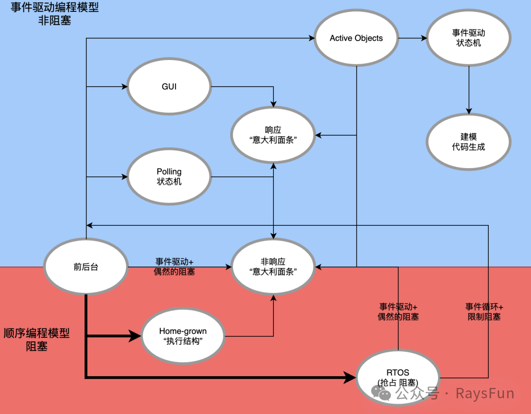
To briefly review, the previous article (Embedded RTOS – Front and Back Architecture) introduced the basic architecture of front and back. It can be implemented using sequential blocking code or event-driven non-blocking code. The following diagram shows these two programming models and their variants. Clearly, RTOS belongs to the sequential programming model. We will focus on this later.
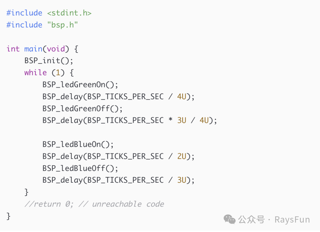
This challenge requires the green LED and blue LED on the LaunchPad board to blink independently and simultaneously. The most straightforward attempt might be to copy and paste the code for the green LED, change it to the blue LED, and use a different delay. However, after compiling and downloading, it is found that both LEDs do indeed blink, but not simultaneously; rather, they light up sequentially — first green, then blue. This is the inevitable result of sequential code.
To make the
LEDs truly independent and blink simultaneously while maintaining a simple sequential structure, we need to run two background loops concurrently. To achieve this, we can create two main functions — <span>main_blinky1</span> and <span>main_blinky2</span>, each with its own while(1) background loop. In the original <span>main()</span> function, reference them to prevent the compiler from optimizing away the unused code. However, note: if they are called sequentially, the compiler will find that the first call never returns, thus optimizing away the second. To avoid this, a <span>volatile</span> variable can be used to conditionally branch the calls. The corresponding project implementation is in lesson-22/tm4c123-keil, main.c with the following code: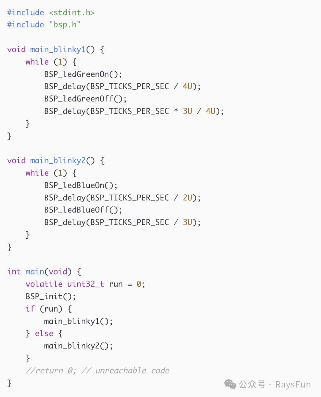
Before running the code, configure the project options:
-
Disable floating-point hardware to simplify interrupt handling and avoid unnecessary floating-point register stack operations.
-
Also ensure that the heap size is non-zero, as the Keil debugger may require it to support features like “semihosting”.
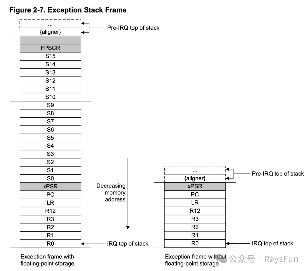
In the debugger, it is found that <span>main_blinky2()</span><span> is running and blinking the blue</span><span><span> LED.</span></span><span><span> To better understand the underlying mechanism, set a breakpoint at the end of the </span></span><code><span>bsp.c</span> in the <span>SysTick</span> interrupt handler (this interrupt triggers 100 times per second). After hitting the breakpoint, open the Memory1 view, dock it to the side, and scroll to the stack pointer (SP). Refer to the TivaC data manual (https://www.ti.com/tool/EK-TM4C123GXL) for the interrupt stack frame layout, as shown in the following diagram. Since the ARM stack grows towards lower addresses, it needs to be viewed in reverse. You will find that the 7th item from the top is the program counter (PC), which will be loaded when returning from the interrupt. This can be verified by stepping through the <span>BX lr</span> instruction.
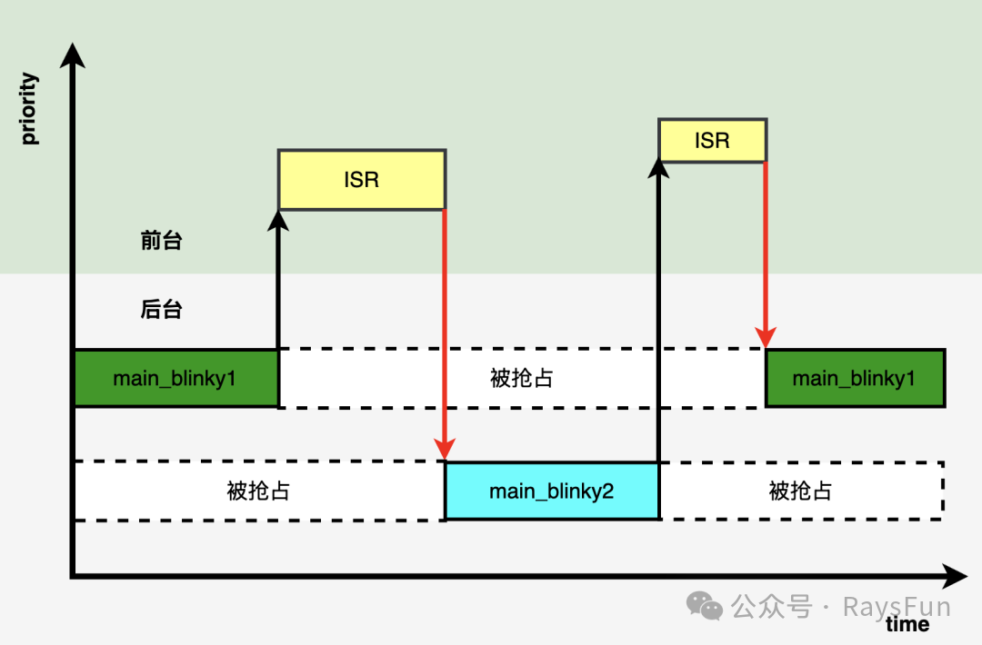
A small trick: when the <span>SysTick_Handler</span> hits again, change the return address on the stack (PC item) to the address of <span>main_blinky1()</span> (for example, 0x7C6). Then step through the interrupt return instruction, and you will find it jumps to <span>main_blinky1()</span>, causing the green LED to start blinking, as shown in the timing diagram below. This indicates that switching between background loops can be achieved through interrupts and stack operations. However, this method is illegal and unreliable in more complex programs.
The above operations validate:
-
It is feasible for the CPU to switch between multiple loops.
-
Context switching can be implemented using interrupt hardware.
-
This is the basic idea of multitasking — allowing the CPU to switch execution between independent threads.
This process can be automatically handled by the real-time operating system kernel (RTOS Kernel), as illustrated in the diagram below.
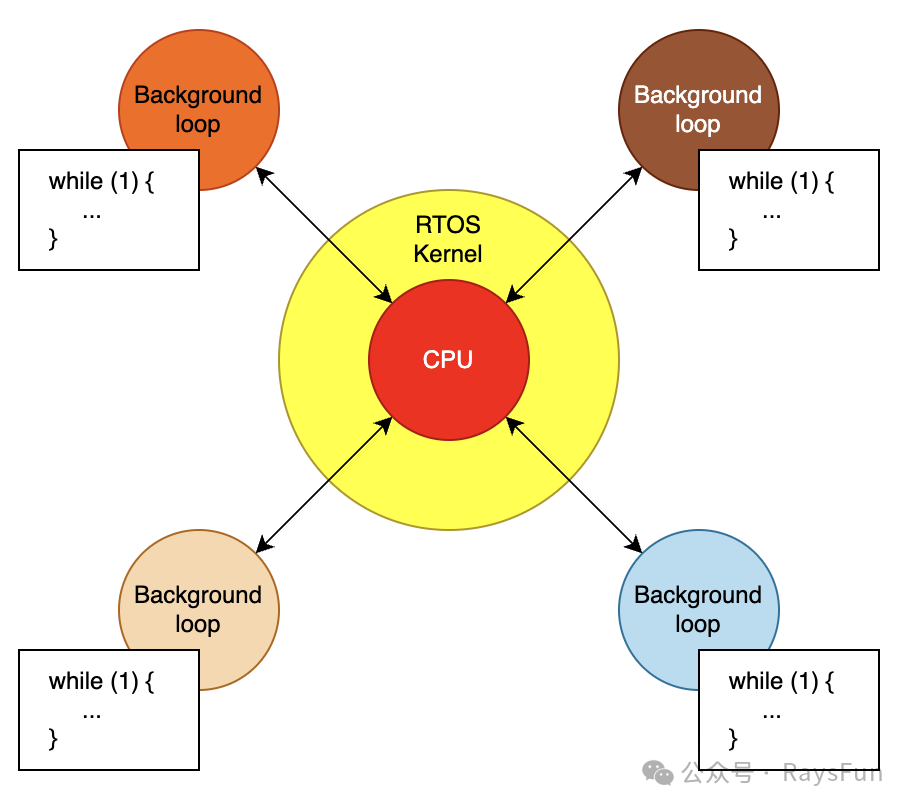
Thus, the RTOS kernel can be simply defined as: software that extends the front and back model, allowing multiple background loops (called threads or tasks) to run on a single CPU. Multithreading or multitasking involves frequent switching of the CPU context, making each thread appear to have exclusive access to the CPU.Note: Threads are essentially the background loops in the front and back model.
Issues with Manually Modifying the Return Address (PC)
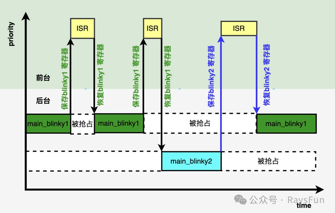
Returning to the issue of manually modifying the return address (PC), during normal interrupts, the context of the same thread is saved and restored. However, if switching from <span>blinky1</span> to <span>blinky2</span>, it is actually restoring the registers of <span>blinky1</span> while executing <span>blinky2</span> — this is clearly incorrect, as shown in the diagram below. It can work in simple cases, but complex code (using more registers) will lead to errors.
The solution is to maintain independent stacks for each thread. In C language, this is straightforward: allocate a <span>uint32_t</span> array as a stack for each thread, with a pointer to the top of the stack. During initialization, set the stack pointer to point to the end of the array (ARM stacks grow downwards). Then, in the main code, do not directly call the thread functions, but instead forge a stack frame that looks like the state just before it was preempted. This includes setting xPSR (the 24th bit for THUMB state) and the function address (cast to <span>uint32_t</span>) as the PC.
Other registers are temporarily irrelevant and can be filled with easy-to-debug values. After setting up the stacks for the two threads (<span>blinky1</span> and <span>blinky2</span>), let <span>main()</span><span> enter an infinite loop, initially doing nothing. In the debugger, check the stacks and pointers. Then set a breakpoint at the end of </span><code><span>SysTick</span>, and when hit, manually set the SP to <span>sp_blinky1</span>, switching to the green LED thread. After running, you will see the green LED blinking.
To switch to <span>blinky2</span>, again under the <span>SysTick</span> interrupt, first save the current SP to <span>sp_blinky1</span>, then set the SP to <span>sp_blinky2</span>. Continue running, and now the blue LED starts blinking. You have just manually completed a context switch. This can be repeated. The key is that each time you return to a thread, it can continue executing from where it was preempted, as the stack has been fully preserved.
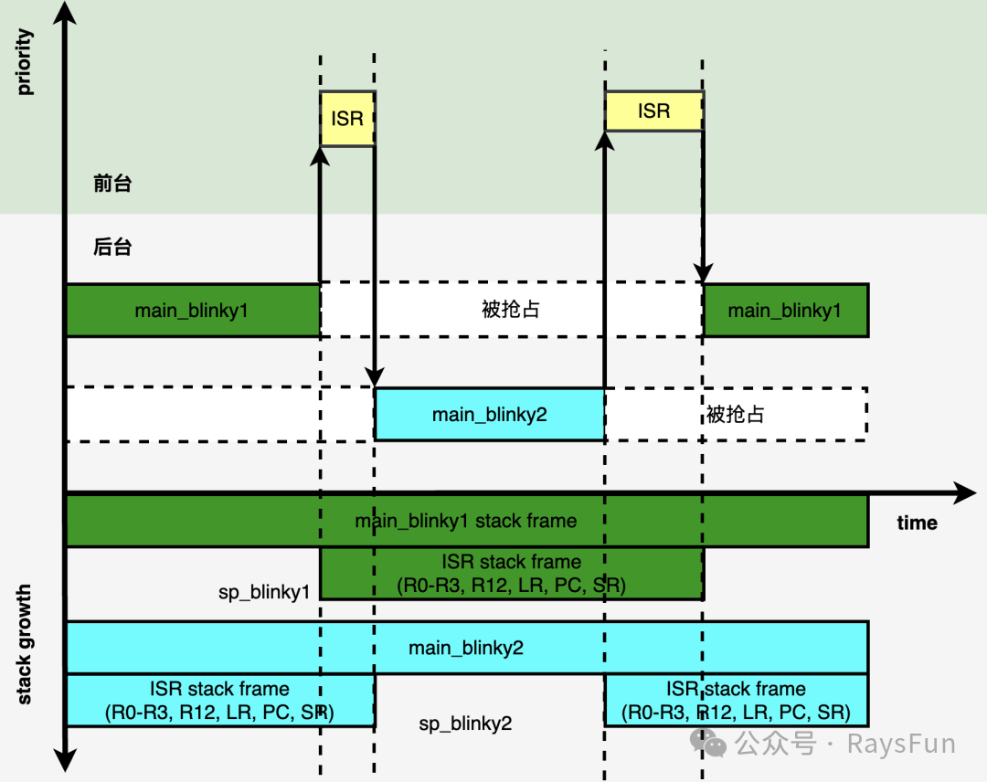
As shown above, the updated timing diagram displays the correct context switching. Registers are saved and restored from their respective thread stacks. However, it is not over yet. The switch has not saved all CPU states. The ARM exception frame only saves volatile registers (R0–R3, R12, LR, PC, xPSR), without saving non-volatile registers R4–R11, which must also be preserved.
If <span>blinky1</span> uses R7 but does not save it, <span>blinky2</span> may overwrite it, as shown in the diagram below.

The solution: before switching context at the end of <span>SysTick</span>, save R4–R11, and restore them upon return. This requires a few more steps: allocate an additional 8 register spaces for each thread stack, update the SP during switching, and ensure the register states are correct. The complete implementation can be found on github (https://github.com/QuantumLeaps/modern-embedded-programming-course/blob/main/lesson-22/tm4c123-keil/main.c)

Conclusion:
Manual management is cumbersome — this is precisely the purpose of automation. The next article will introduce how to build an RTOS kernel that automatically handles these details. The core point of this article is to understand what RTOS threads are and how the kernel switches the CPU context between them.