This article discusses the three main elements of tasks: task control blocks, task stacks, and task entry functions, and highlights three important considerations when writing RTOS task entry functions.
1. Knowledge Review
Before we officially start explaining the content, I will first review some basic knowledge points. Please ensure you have understood and mastered them.
1.1. Task Creation Methods
To create a task at the user level, the usual process is as follows:
① Create an array as the task stack:
#define TASK1_STACK_SIZE    512
k_stack_t task1_stack[TASK1_STACK_SIZE];
② Create a task control block:
k_task_t task1;
③ Write the task entry function:
void task1_entry(void *arg)
{
    while(1)
    {
        printf("task1 is running\r\n");
        tos_task_delay(1000);
    }
}
④ Call the system API to create the task:
ret = tos_task_create(&task1,
                      "task1",
                      task1_entry,
                      NULL,
                      TASK1_PRO,
                      task1_stack,
                      TASK1_STACK_SIZE,
                      10);
After creation, the task is in a ready state (in the system ready queue), waiting for the system scheduler to schedule execution.
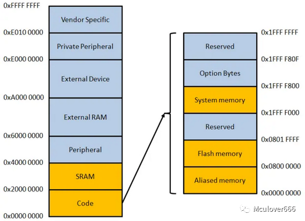
1.2. STM32 Memory Distribution
Please read the article:
- Analysis of STM32 Memory Allocation and Variable Storage Locations
After reading, you should know that the memory space of Flash and SRAM in STM32 (Cortex-M3) is as follows:
 In the Flash storage space, it is further divided into text segments, read-only data segments, and copy data segments:
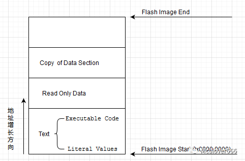 In the SRAM storage space, it is divided into data segments, bss segments, heap space, and stack space:
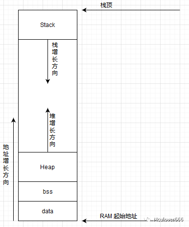 You should also know where different variable types correspond to their storage locations. If you do not, be sure to read the previous article and come back to this one, as it is the foundation for understanding the subsequent content.
1.3. Cortex-M3/4 Series Cores
The register set in the Cortex-M3/4 series cores consists of 16 registers, as shown in the figure. The register set is typically used by the CPU for data processing and execution control. It is hoped that you can have a general understanding of the function of each register:
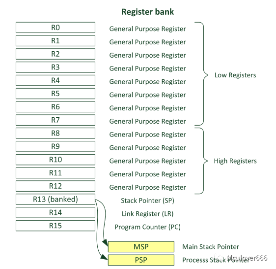 ① R0-R12: General-purpose registers used for data operations;
② R13: Stack pointer, with two mutually exclusive pointers MSP and PSP, only one of which can be used at any time;
③ R14: Link register, stores the return address when calling a subroutine;
④ R15: Program counter, where the PC pointer points, the CPU executes the code at that location;
In the RTOS kernel, the values of these 16 registers are referred to as “context”. The values of these 16 registers during the current task’s execution are called the upper context, while the values of these 16 registers during the next task’s execution are called the lower context. “Context switching” refers to modifying the values of these 16 registers to those of the next task.
1.4. Stack
A stack is a “data structure that can only insert or delete elements at one end”, with the rule being: “last in, first out” (FILO).
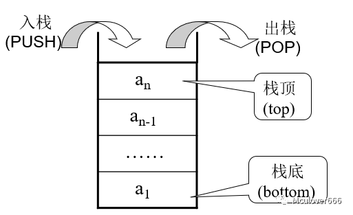 During the execution of a C program, the stack is extremely important. In bare-metal programs, the stack pointer is provided by register R13.
The stack serves two main purposes: on one hand, it stores local variables. The definition of local variables will be assembled into PUSH instructions, pushing the contents of local variables onto the stack, and after the function execution is completed, they are popped from the stack, and the local variable is destroyed; on the other hand, it is used for passing parameters during function calls, which are also pushed onto the stack and popped after the function execution is completed.
2. What Does a Task Control Block Look Like?
The task control block is the core of a task. Broadly speaking: “All operations on tasks by the kernel are actually operations on the task control block”.
The task control block type k_task_t is a structure type:
typedef struct k_task_st k_task_t;
When a task control block is defined, the structure variable has no initial value, so “the storage location is in the bss segment of the internal SRAM of STM32”.
The structure type of the task control block is defined as follows:
/**
 * task control block
 */
struct k_task_st {
    k_stack_t          *sp;                     /**< task stack pointer. This lady always comes first, we count on her in port_s.S for context switch. */

    knl_obj_t           knl_obj;                /**< just for verification, test whether current object is really a task. */

    char                name[K_TASK_NAME_MAX];  /**< task name */
    k_task_entry_t      entry;                  /**< task entry */
    void               *arg;                    /**< argument for task entry */
    k_task_state_t      state;                  /**< just state */
    k_prio_t            prio;                   /**< just priority */

    k_stack_t          *stk_base;               /**< task stack base address */
    size_t              stk_size;               /**< stack size of the task */


    k_list_t            stat_list;              /**< list for hooking us to the k_stat_list */

    k_tick_t            tick_expires;           /**< if we are in k_tick_list, how much time will we wait for? */

    k_list_t            tick_list;              /**< list for hooking us to the k_tick_list */
    k_list_t            pend_list;              /**< when we are ready, our pend_list is in readyqueue; when pend, in a certain pend object's list. */

    pend_obj_t         *pending_obj;            /**< if we are pending, which pend object's list we are in? */
    pend_state_t        pend_state;             /**< why we wakeup from a pend */
};
❝
The source code quoted here is “incomplete”, all definitions configured with macro switches are omitted for readability.
❞
The contents of the task control block are mainly divided into three parts:
① Task stack top pointer sp: will be explained in detail later;
② All information about the task: task name, task state, task priority, task entry function and parameters, task stack address and size;
③ Task linked list: will be explained in detail in subsequent articles.
3. Task Stack
3.1. What is a Task Stack?
The task stack type k_stack_t is of type uint8_t:
typedef uint8_t k_stack_t;
When a task stack array is defined:
#define TASK1_STACK_SIZE    512
k_stack_t task1_stack[TASK1_STACK_SIZE];
Essentially, it is still a global variable array of type uint8_t, and this global variable array has no initial value, so “the storage location is still in the bss segment of the internal SRAM of STM32”.
When using this array, it is accessed only through the pointer sp, pretending it is a stack, and it is used in exactly the same way as a stack, hence it is called a task stack.
3.2. What is in the Task Stack (Function)?
In the API for creating tasks, there is a line of code to initialize the task stack and return the task stack top pointer sp:
task->sp = cpu_task_stk_init((void *)entry, arg, (void *)task_exit, stk_base, stk_size);
Looking at the definition of cpu_task_stk_init, you will find that “the implementation of this function varies for different CPU architectures”.
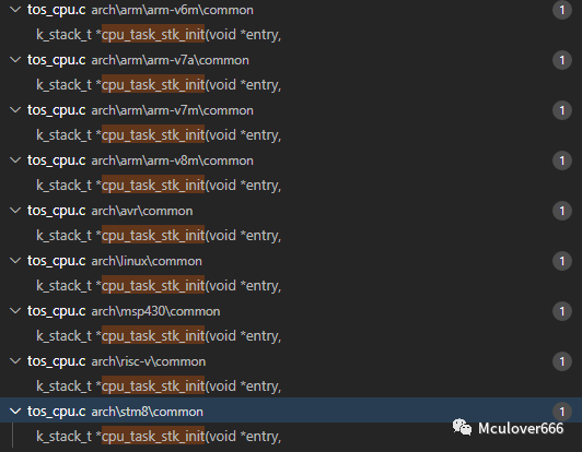
Why does the task stack initialization code implementation differ for different CPU architectures?
Don’t worry, let’s first look at how to initialize the task stack. “The Cortex-M series chips correspond to the ARM v7m architecture”, we will explore the implementation of the cpu_task_stk_init function in this architecture to find the answer.
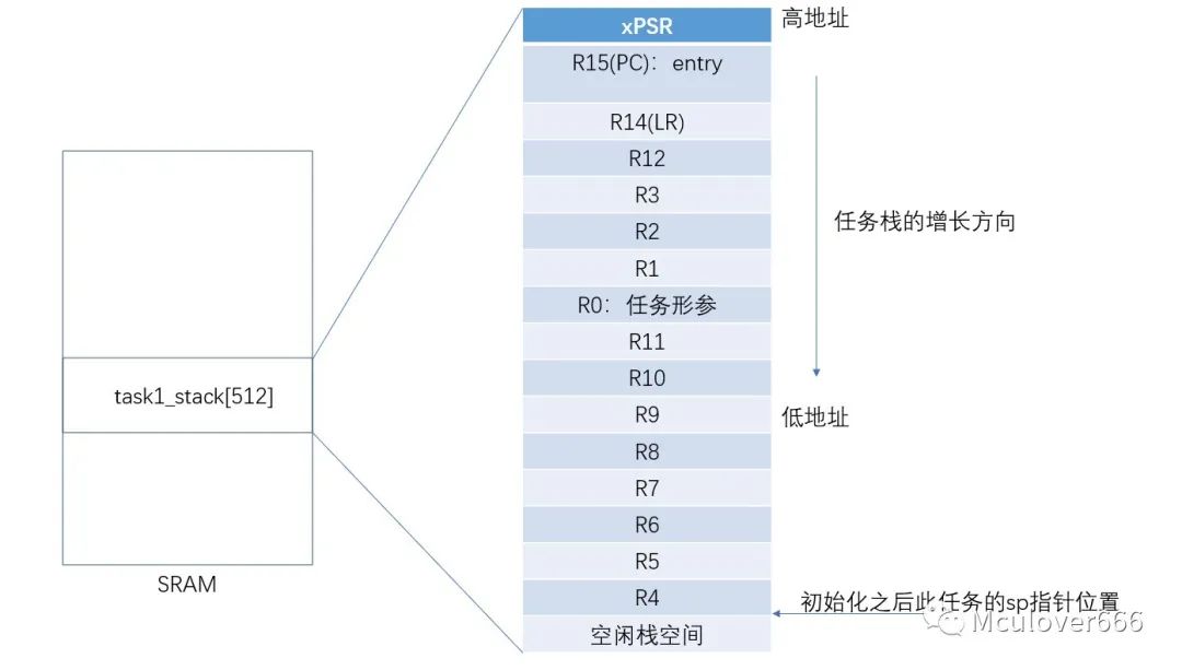
① Get the address of the task stack top pointer and align it:
cpu_data_t *sp;

sp = (cpu_data_t *)&stk_base[stk_size];
sp = (cpu_data_t *)((cpu_addr_t)sp & 0xFFFFFFF8);
② Registers automatically saved during PendSV exception:
/* auto-saved on exception(pendSV) by hardware */
*--sp = (cpu_data_t)0x01000000u;    /* xPSR     */
*--sp = (cpu_data_t)entry;          /* entry    */
*--sp = (cpu_data_t)exit;           /* R14 (LR) */
*--sp = (cpu_data_t)0x12121212u;    /* R12      */
*--sp = (cpu_data_t)0x03030303u;    /* R3       */
*--sp = (cpu_data_t)0x02020202u;    /* R2       */
*--sp = (cpu_data_t)0x01010101u;    /* R1       */
*--sp = (cpu_data_t)arg;            /* R0: arg  */
③ Manually saved/loaded registers:
*--sp = (cpu_data_t)0x11111111u;    /* R11      */
*--sp = (cpu_data_t)0x10101010u;    /* R10      */
*--sp = (cpu_data_t)0x09090909u;    /* R9       */
*--sp = (cpu_data_t)0x08080808u;    /* R8       */
*--sp = (cpu_data_t)0x07070707u;    /* R7       */
*--sp = (cpu_data_t)0x06060606u;    /* R6       */
*--sp = (cpu_data_t)0x05050505u;    /* R5       */
*--sp = (cpu_data_t)0x04040404u;    /* R4       */
④ Return the current stack top pointer:
return (k_stack_t *)sp;
After initialization, the contents of the task stack are as follows:
The general process of task switching is triggered by the PendSV exception, and the task switching is implemented in the exception handler using assembly language, which is “context switching”. The next article will specifically discuss task switching.
When the task is scheduled for execution, the CPU automatically loads the values of the first eight registers from the task stack into the CPU registers, completing the “lower context switch”. At this point:
- The value in the stack pointer register R13 is the sp pointer of the task’s task stack;
- The program counter pointer PC points to the entry function of the task;
At this point, the environment in the CPU is that of the task, and the task begins to run.
Since the stack pointer points to the task’s task stack, if parameters are passed, functions are called, or local variables are created in the task’s entry function, “all data is pushed onto the task’s task stack”, which has no relation to the internal stack space of STM32.
Similarly, when the task is completed (not necessarily the end of the program, but when the scheduler needs to schedule other tasks), because the stack follows the “last in, first out” rule, the CPU will push the current register group values onto the stack, completing the “upper context save”. The next time these register group values are needed, they will be popped from the stack first.
Finally, the answer to the question is that “different CPU architectures have different numbers and functions of CPU register groups”, so an implementation is needed for each CPU architecture.
4. How Should a Task Be Written?
When learning RTOS, our focus is often on “how to create tasks”, placing emphasis on the task creation API while neglecting some of the most important issues.
Key Point ①: “The task entry function is not an ordinary function”.
The task entry function often disguises itself as an ordinary function, unlike the main function that stands out, so many times we think it is just an ordinary function call, but it is not.
“Each task’s entry should first be an independent bare-metal program.”
Why do I say this? Because the mechanism of a multitasking operating system is preemptive scheduling and time-slicing. No matter how powerful it is, it cannot change the fact that there is only one CPU in the system, so at any given moment, there is only one task running in the system.
Key Point ②: “Every line of code written must consider whether the task stack is sufficient”.
Local variables created in the task entry function, function calls, and function parameters all use the task’s task stack, which has no relation to the internal stack space of STM32. Therefore, when writing, you must always consider whether the specified task stack size is sufficient, especially when allocating local variable arrays or calling some library APIs.
In addition, if static variables are defined in the task entry function, they will not be stored in the task stack but will be stored in the bss area of the internal SRAM of STM32.
Other than that, the remaining code belongs to executable code, stored in the Flash text area in the Executable Code segment, and does not need to be overly concerned about.
Key Point ③: “Always try to yield the CPU actively, avoid wasting CPU”.
In bare-metal programs, if you like to write a busy-waiting loop for delays, it can be forgiven, but in an RTOS system, if a task is in a busy-waiting loop doing useless work, preventing other tasks from being scheduled for execution, it is unforgivable.
When writing the task entry function, you must adhere to the principle of “if not used, yield” to be a high-quality task. The most common practice is to use the system-provided delay function to delay.
This approach has many advantages: on one hand, it prevents the system from blocking, causing other tasks to be unable to run; on the other hand, it allows idle tasks in the system to reclaim system memory resources and enter low-power modes, among other operations.
This section concludes here. I hope it is helpful to you. I am Mculover666, a small programmer who enjoys working with boards. See you in the next article~
“To receive more exciting articles and resource updates, please subscribe to my WeChat public account: ‘mculover666’.”