The Russia-Ukraine war has been ongoing for over three years, with the front lines shifting back and forth, and there have finally been some significant changes recently. The two beautiful Russian ladies who used to frequently appear in the neighborhood are no longer seen.
However, my proficiency in Russian and Ukrainian has not changed much.
To reverse this unfavorable situation, I still need to learn from Tony, who sells LED lights, and study more foreign languages, as well as read more papers in Russian and Ukrainian.
So today, I will first use machine translation to translate a paper from Samara State Aerospace University (Самарский государственный аэрокосмический университет имени академика С.П. Королева, renamed Samara National Research University after 2016).
This paper focuses on the automated testing of airborne avionics equipment for drones by the Kronstadt Group (Кронштадт).
The authors of this article are students and teachers from the Aerospace Department of Samara State Aerospace University and the head of the testing department of the Kronstadt Group. This university is located in Samara and is named in honor of the famous Soviet rocket and space systems chief designer Sergey Pavlovich Korolev (Серге́й Па́влович Королёв).
This article and subsequent machine translations will have many inaccuracies, and it is estimated that it will take 1-2 years to gradually reduce errors. The main purpose is to learn the language, and it may not yet be suitable for your electronic pickled vegetables.
Before introducing the content of this article, let’s first provide some background information about Kronstadt.
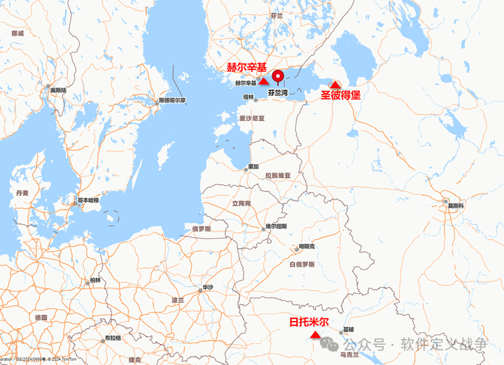
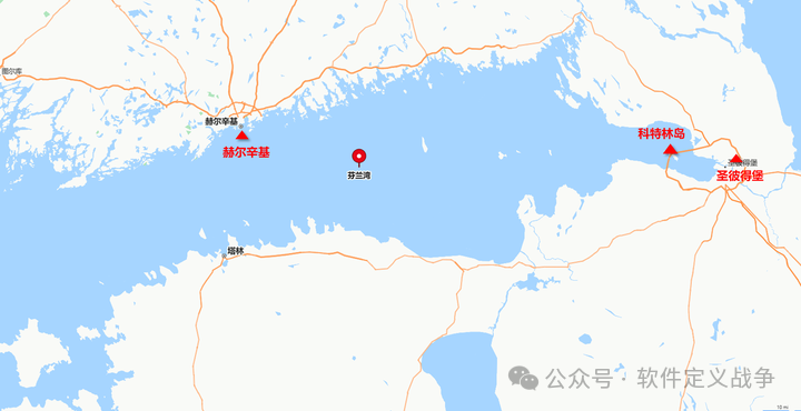
The Kronstadt Group is a major drone manufacturer in Russia, named after the city of Kronstadt, located near the Gulf of Finland. Kronstadt is a naval fortress ordered to be built by Tsar Peter the Great on Kotlin Island (1703) to protect the Russian capital of St. Petersburg and the Neva River delta.
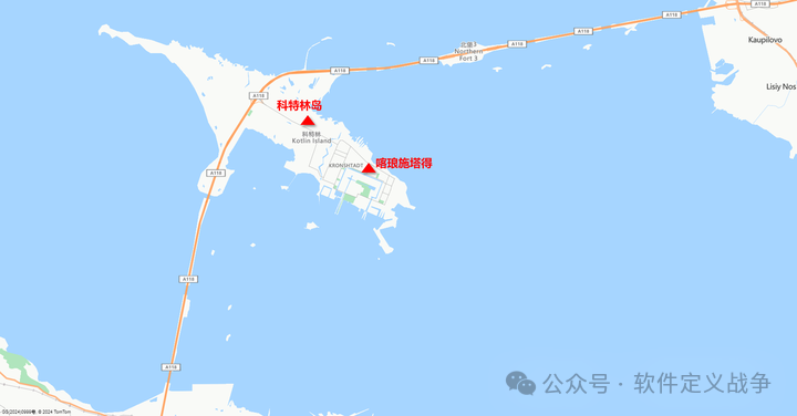
So where is Kronstadt? It is located on Kotlin Island, about 30 km to the left of St. Petersburg in the image below.
As shown in the image below, the marked location is surrounded by islands connected by a cross-sea highway. Kotlin Island guards the routes for Russia’s access to the Baltic Sea. The city of Kronstadt is built on Kotlin Island and is a city under the jurisdiction of St. Petersburg.
The Kotlin programming language on the Java Virtual Machine is named after this island, just as the Java language is named after the Indonesian island of Java. The Kotlin language was developed by JetBrains, a company founded by three Russian programmers, whose R&D team is located in St. Petersburg.
The Kronstadt fortress is built on Kotlin Island. Before 1996, foreigners were not allowed to stroll around.
The Kronstadt has always been the home port of the Baltic Fleet of the Russian Empire, the former Soviet Union, and Russia. During the Russo-Japanese War, the Russian Navy fleet set sail from here, rounding the Cape of Good Hope and the Indian Ocean to reach the Far East. Historically, the famous Kronstadt sailors’ “rebellion” (1921) occurred here, which was suppressed by Tukhachevsky, one of the founders of the Soviet Red Army, known as the “Red Napoleon”.
Tukhachevsky led the Red Army to eliminate the main forces of the White Army led by Kolchak and Denikin during 1919-1920. In 1921, he was ordered to suppress the Kronstadt sailors’ rebellion.
After becoming a marshal, Tukhachevsky was in charge of the development of Red Army equipment. He supported Tupolev’s aircraft design work and assisted Korolev’s rocket research.
Korolev’s mother was Ukrainian, and his father was Russian. He was born in 1907 in Zhytomyr, the capital of Zhytomyr Oblast in northwestern Ukraine.
A granite statue of Korolev stands in front of the city hall in Zhytomyr. After the start of the Russia-Ukraine conflict, large boxes labeled “Starlink” were moved into the mayor’s office of Zhytomyr City Hall for emergency communication use. The armored vehicle factory in Zhytomyr was also bombed by Russian missiles. Zhytomyr Oblast also has rare earth mines that are to be mined for the United States.
Korolev, standing in front of the Zhytomyr City Hall, probably never imagined that the arms factory in his hometown would be bombed by Russian missiles while the American Starlink was receiving NATO intelligence in his hometown’s city hall.
In 1926, Korolev became a student of aircraft designer Tupolev.
In October 1933, Korolev was appointed deputy director of the Leningrad Institute of Aerodynamics. This institute was established with the support of Tukhachevsky and was the world’s first jet science research institute dedicated to rocket technology research.
In 1937, due to a plot by art students, Marshal Tukhachevsky and seven other senior Red Army leaders were sentenced to death for “espionage.” The rocket technology research institutions and rocket experts created and supported by Tukhachevsky were also implicated.
In 1938, Korolev was accused of “participating in an anti-Soviet organization” and sentenced to eight years of hard labor, being sent to the Kolyma gold mine labor camp in Siberia for supervision. Tupolev was also arrested as a “people’s enemy” at the KGB headquarters in Moscow, Lubyanka (Лубя́нка).
Tupolev was subsequently imprisoned in the Ministry of Internal Affairs’ 29th Central Design Bureau, where he designed the Tu-2, the best twin-engine multipurpose propeller medium bomber of World War II, with a group of “prisoner” designers.
After the outbreak of the Soviet-German War in 1941, the Soviet military re-employed weapon technology experts. Korolev was transferred to the aviation department, where he conducted experimental research on installing jet engines on aircraft under the leadership of chief designer Tupolev.
In July 1944, the Supreme Soviet of the Soviet Union decided to conditionally release rocket experts and technology experts arrested during the “Great Purge.” Korolev was transferred to continue his rocket research.
The Linux operating system founder Linus Torvalds and MySQL database founder Michael Widenius were both born in Helsinki, the capital of Finland, located to the left of St. Petersburg.
Thus, St. Petersburg, the Kronstadt sailors’ rebellion, Tukhachevsky who suppressed the Kronstadt sailors’ “rebellion,” Korolev born in Ukraine, the Samara State Aerospace University established in memory of Korolev, the automated testing of drones by the Kronstadt Group, Linux and MySQL from Helsinki, the Western aid in the Russia-Ukraine conflict, and the Western aid in the Winter War (Зимняя война) are all intriguingly connected.
Having digressed, let’s return to this article. Through this article, one can understand the automated testing of Russian military drones and gain insight into the Russian military software supply chain.
1. Overview
The airborne embedded real-time system (ВСРВ, встроенные системы реального времени) is a multi-machine computing system installed on the latest generation of drones. The communication channels between products in ВСРВ can reach dozens. During the testing phase of ВСРВ, there are several tasks that require tool support, including:
-
Verifying whether ВСРВ products meet technical specifications, such as receiving and transmitting data through external interfaces;
-
Testing the interaction between different components of ВСРВ through onboard data transmission channels;
-
Conducting comprehensive tests on the software security of ВСРВ;
-
Assessing the reliability of the ВСРВ architecture, evaluating the availability of backup capacity in data transmission channels, evaluating the soft and hardware of ВСРВ during data transmission failures, and assessing the reliability of individual system components;
-
Creating a data exchange schedule for the onboard transmission channels and verifying the correctness of the execution of that schedule by various components within ВСРВ.
The development of the product components included in ВСРВ is mostly carried out by different organizations. The testing preparations for different products occur at different times. To meet the deadline for manufacturing finished products, preliminary testing with a set of testing equipment is necessary.
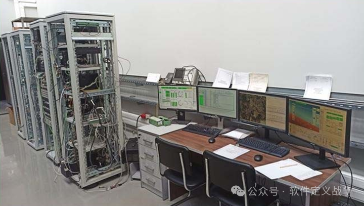
This article describes a hardware-software complex—a semi-physical modeling (ПНМ, полунатурного моделирования) test bench for airborne ВСРВ. This test bench can connect to digital simulation models (simulators) or physical products of the equipment. This allows for phased integration and testing of different devices on ВСРВ—first testing with mathematical simulation models, and then replacing them with physical devices for testing once the physical products are ready.
2. Overall Structure of the Test Bench
The airborne equipment integration of the ПНМ (semi-physical simulation) test bench is divided into two stages:
1) In the first stage, integration is primarily based on digital model simulation. Most of the design work is carried out in this stage.
2) In the second stage, integration is primarily based on physical devices. As many simulation models on the test bench as possible are replaced with physical devices.
This method allows for comprehensive development and testing work based on the combination of physical and simulated devices. This way, the number of detected errors can be minimized during the comprehensive testing phase.
The following image shows the overall structure of the test bench.
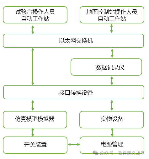
Automated Workstation
The main operating interface of the test bench is the automated workstation (АРМ, Автоматизированное рабочее место) used by the ground control station (НПУ, наземного пункта управле- ния) operators, a PC running version 1.7 of the AstraLinux operating system, used for testing the drones.
The main functions of the automated workstation are as follows:
-
Setting up automated test scenarios, selecting digital simulation models and physical products;
-
Setting registration parameters;
-
Monitoring the operation of the experiment, including displaying the parameter values of the simulation model and showing the experimental results;
-
Analyzing experimental results, including the change curves of simulation model parameter values and event logs in the simulation model and transmission channels.
AstraLinux (see Appendix A) is a Linux distribution developed by the Russian company RusBitTech based on Debian GNU/Linux, used in the Russian military, intelligence agencies, and other government institutions where information security and data protection are of high importance. Its purpose is to replace foreign operating systems like Windows to ensure the security of Russia’s critical information infrastructure.
One of the main features of AstraLinux is its security. It integrates the Russian national encryption algorithm GOST, provides a highly customizable kernel, and enhances system security. It also implements a complete security solution independent of standard mandatory access control (MAC) mechanisms, such as PaX patches.
Data Logger
Reads data from interface conversion devices using TCP and UDP protocols and saves it.
Interface Conversion Device
A PC with a data transmission channel controller is used to transmit simulation data from the simulation system to the airborne equipment information system and to forward the output signals from the airborne equipment to the simulation program in the simulator. The main interface protocols used are: MKIO, arinc429, one-time commands for drones (разовые команды), arinc646, arinc818 (see Appendix B).
Simulation Model Simulator
Provided by the developers of the ВСРВ products. There are two main versions:
-
A PC with a digital simulation model and necessary data exchange channel controllers
-
A simulated ВСРВ product with data exchange interfaces
Switching Device
Can connect physical products and simulators. Operators control it through the АРМ (automated workstation).
Supports two operating modes:
-
Manual mode: The operator manually selects the data transmission channel;
-
Automatic mode: Automatically loads files with pre-configured scenarios.
3. Improvements in Testing Methods
3.1 Original Testing Method
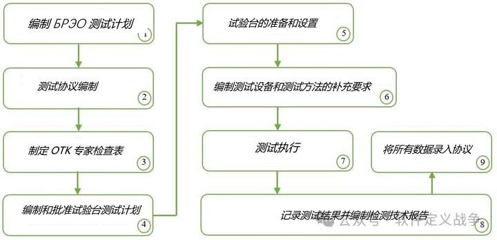
The testing of the drone’s airborne equipment complex on the ПНМ (semi-physical simulation) test bench is carried out according to the following steps (see the image below).
Upon receiving the airborne avionics equipment (БРЭО, бортового радиоэлектронного оборудования) products from suppliers at Kronstadt, an external mechanical damage inspection is first conducted.
Experts from the technical control department (OTK, отдела технического контроля) check whether the products comply with the accompanying documents, and then the products are transferred to the test bench.
Depending on the number of finished drones, they are installed on the test bench and parameter configurations are made.
The test bench is powered on, including the PC, industrial computer, and dedicated simulation software for the simulator, and the hardware power of the test bench is manually turned on.
Using the software, the configuration file is opened to run the simulation model, and the data source (simulation model simulator/physical device) is selected.
At this point, the preliminary setup is complete, and the testing process begins.
Testing is conducted according to the manual, with a single test step potentially involving up to thirty steps.
After testing is completed, the results are processed, and a report is submitted to the client and experts from the technical control department.
Then, without a computer, the test results are entered into the company’s technical regulatory documents (protocols).
Finally, the power to the test bench is cut off, and the tested products are removed from the test bench.
3.2 Existing Problems
For small-scale production testing, the above scheme is feasible. However, using this testing method at the Kronstadt Group presents the following two issues.
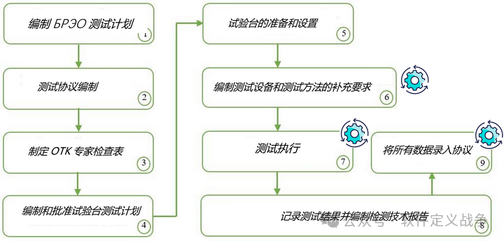
First, due to the company’s start of mass production, the number of products to be tested has significantly increased, resulting in a large testing workload. The frequently performed operations (5) and (7) (see the image above) are the most labor-intensive steps.
Second, since the tested devices are all digital electromechanical devices, but the documentation records of the tests are done on paper, this increases the workload and may lead to errors during manual entry.
3.3 Improvement Goals
To address the above issues, two goals have been proposed:
1. Development of technology for automated power management and switching devices. This improvement will reduce manual operations (power on/off, switching interfaces of tested devices) and reduce the standard testing time for a БРЭО (airborne avionics equipment) set by at least 15%. If production increases, a significant amount of time will be saved.
2. Development of an IT information system for test planning and execution, digitizing and automating the work of the testing department, and improving the data quality of drone equipment testing.
3.4 Solutions
To achieve the above goals, the existing test bench can be modified to conduct automated testing of airborne embedded systems.
Therefore, by using additional technologies and software tools, the automation of steps (6), (7), and (9) (see the image below) can be achieved.
-
Using automatic power control;
-
Automatically switching the use of devices;
-
Managing test data (input parameters, test result data) in a database, and developing applications based on the database for automated testing.
Automatic power control and automatic switching devices are not covered in this paper.
This article focuses on the design of database-based automated test management software.
The database stores information about the tested devices (software versions of the tested units, update dates, versions of software and information exchange protocols, test values, and parameters that may be added during the development phase). The system database will be updated by employees of the electronic equipment department.
The automated workstation of the test bench can automatically execute tests according to the test scenarios and automatically generate electronic documents of test result reports with unit serial numbers, test dates, and times.
System Use Case Design
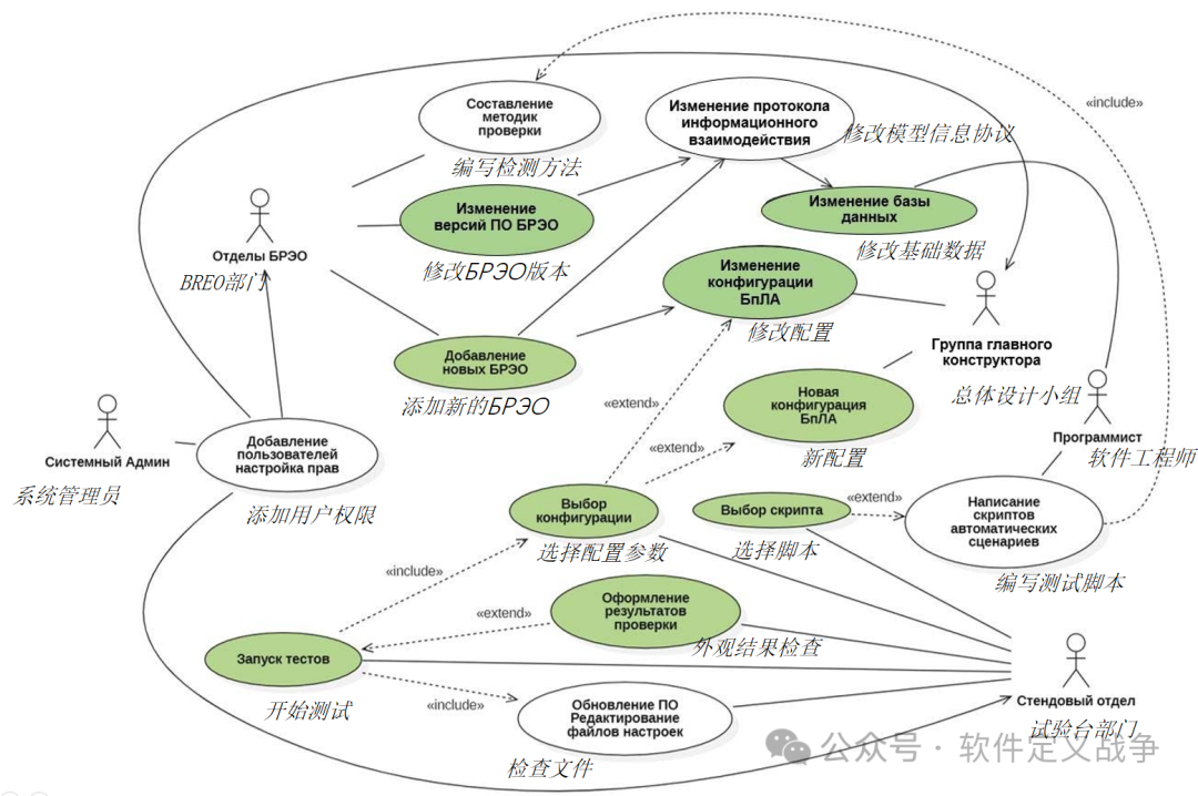
The following image shows the UML use case diagram of the automated testing information system, describing the main use cases of various service departments involved in testing airborne equipment.
The actors of different use cases include:
-
Overall Design Team
-
Test Bench Department
-
Software Engineers
-
БРЭО Electronic Equipment Department
-
System Administrators
Software Architecture Design
The specific architecture design is shown in the following image.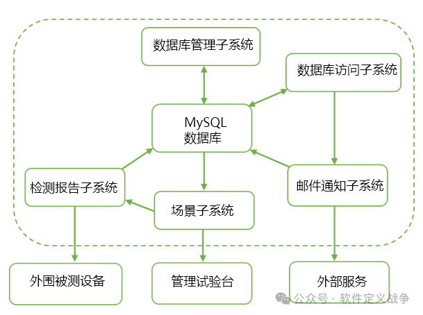
Selection of Software Development Tools
The selection of programming tools should be based on the use of freely distributed open-source software. Generally, it is best to use software included in the Russian software registry at https://reestr.digital.gov.ru/.
At the same time, the selected programming tools should be able to interact with the existing test bench and functional software.
Users primarily access through a browser. The web development framework uses Python’s Django framework. The front-end CSS framework uses Bootstrap.
The database uses MySQL, deployed on a dedicated server connected to the company’s local network.
The scenario subsystem uses C++ and QT.
Reports are developed using the Qt LimeReport reporting library.
Database Access Control
Database users are divided into four categories of roles:
1. Database System Administrator: Has superuser privileges and can perform all operations.
-
Updating database management system software;
-
Adding and deleting users, setting access permissions;
-
Creating backup copies and recovery points;
-
Maintaining security tools;
-
Maintaining management files;
-
Data recovery.
2. Overall Design Team: Adds and modifies drone configurations in the database.
3. Avionics Equipment Department: Adds avionics products in the database, changes avionics software versions, and adds electronic version information exchange protocols.
4. Test Users (including test bench and equipment departments): Have read-only access.
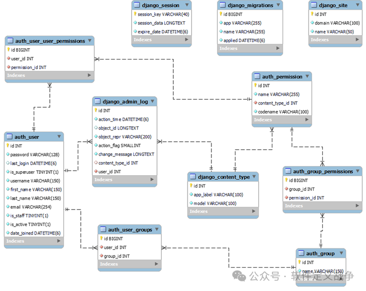
Database Table Structure Design for User Permissions
The user permissions-related table structure in the MySQL database is shown in the following image.
Note: The structure of the critical testing parts is not introduced.
Email Notification Subsystem Design
When data changes in the database, email notifications are sent to relevant personnel. It has the following functions:
-
Sending emails with recipients, subjects, and messages;
-
Mass mailing;
-
Sending attachments;
-
Tracking and handling errors related to sending error messages;
-
Supporting TLS and SSL encryption.
This subsystem is developed based on the Django framework’s Django.core.mail module.
Scenario Subsystem
The testing scenario subsystem is one of the most labor-intensive stages in the testing work. Therefore, it is necessary to develop automated testing methods. This subsystem should implement the following functions:
-
Automatically read and load test input parameters (ICD messages, configurations, scenarios) from the database;
-
Automatically start the simulation program in the simulator;
-
Automate the control of switching on and off for different tested devices (simulators and physical products);
-
Read test result data and automatically compare it with test reference standards;
-
Automatically record the test data of the tested devices and save it to the database.
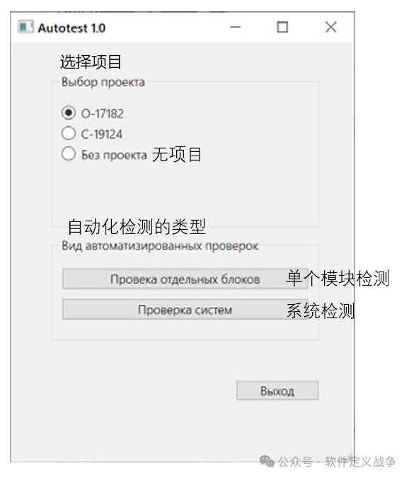
The scenario subsystem has two operating modes (see the image below):
1. Checking a single module: Conducting simple tests on the operability of a single avionics product. The main application is the incoming inspection (IQC) of products received by the Kronstadt company from suppliers.
2. System Testing: Creating a separate inspection scenario to find errors in the interaction logic of the entire system.
-
Mathematical models of the drone’s airborne equipment
-
Simulation data recording modules
-
User graphical interface for manually starting the simulation software executable
This part must use the same programming language and interface library as the current simulation software: C++ and QT. Configuration and module data must be read from the database. Qt QMYSQL is used as the MySQL database driver.
Testing Report Subsystem Design
Generate testing reports based on test result data.
The content of the test result report includes:
-
Testing date;
-
Name of the tested product;
-
Factory number;
-
Test results (success or failure).
The output document (report) must be sent to the printer for printing and saved to the company’s file server.
Reports are developed using the Qt LimeReport reporting library.
Security Design
Protect confidential information stored in the functional system and its subsystems’ databases under development. The following protection mechanisms are required:
-
User authentication and authorization;
-
User access control to the database;
-
Data encryption;
-
Data backup.
When exchanging information between the client and server, middleware is used to prevent CSRF (Cross-Site Request Forgery) attacks. This is activated in the Django framework through the “Django.middleware.CSRF.csrfviewmiddleware” to enable the “CSRF” middleware.
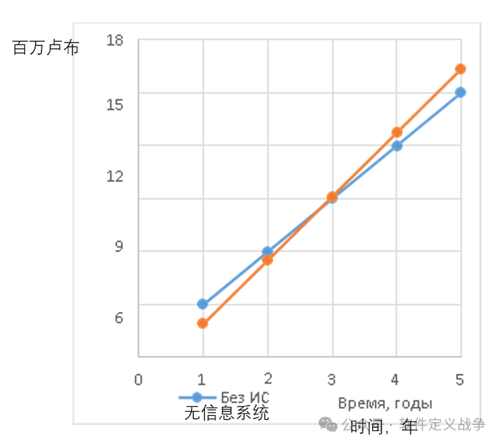
4. ROI Estimation for Automated Testing
This paper also estimates the input-output of the information system (ИС) required for automated testing, with the following results:
-
Operational savings of up to 6.096 million rubles/year
-
Increased profit of 3 million rubles/year (3 млн. р./год)
-
Investment will be recouped in 2.81 years.
Therefore, this automated testing scheme is feasible and recommended for implementation.
Note: The estimation assumes testing 2400 sets of drone avionics equipment annually.
5. Conclusion
The drone market is expected to see a sharp increase in production in the coming years. Therefore, Kronstadt now needs to consider how to reduce the workload and production time of drones.
The testing of drone avionics systems is a component of the drone production process and modernization. The reliability of drone production depends on the quality of testing and the accuracy of the results obtained.
The original testing methods for airborne drone avionics equipment at Kronstadt have a low degree of automation, and their impact will increase with production volume. The automated testing methods proposed in this article can improve testing efficiency and reduce testing costs.
Appendix A: AstraLinux and Software Supply Chain Security (Excerpt from “China Information Security” November 2023)
The Russian government has been working to promote software import substitution since 2014 to reduce its high dependence on software imports.
The Russian software import substitution policy does not simply pursue a 100% domestic software rate but adheres to the principle of self-control. In this principle, self-sufficiency is just one means to achieve controllability, while the ultimate goal of controllability is to ensure national cybersecurity.
The adherence to the principle of self-control in Russian software import substitution is mainly reflected in the following aspects:
First, using open-source software to achieve open-source innovation. Given the vast number of products in the software industry, it is difficult to achieve complete self-innovation, so Russia has chosen to utilize mature open-source software to achieve security and controllability. For example, to develop a truly self-controllable operating system based on Linux open-source code, the Federal Technical and Export Supervision Bureau and the Institute of System Programming of the Russian Academy of Sciences established the Linux Security Research Center in March 2021, focusing on researching vulnerabilities in Linux to ensure the security of the domestically produced operating system Astra Linux based on the Linux kernel.
Second, building a domestic software ecosystem. In the short term, it is impossible to significantly reduce the import rate of information and communication hardware facilities, so building a domestic software ecosystem has become the main approach to achieving self-control in the information and communication field. Based on the development of a basic operating system using open-source software, efforts are being made to significantly increase the domestic rate of related application software, gradually constructing a good domestic software ecosystem.
Third, vigorously supporting domestic core software enterprises. Domestic core software enterprises are key forces in achieving software self-innovation and are the focus of support in the field of Russian software import substitution. For example, the Russian government provides priority procurement, special fund guarantees, tax incentives, and other support for RusBITech, the company that developed the Astra Linux operating system.
Appendix B: Aviation Interface Protocols
Below is a detailed introduction to MKIO, ARINC429, one-time commands for drones, ARINC646, and ARINC818.
MKIO
MKIO (Motorola Kernel Input/Output) is an input/output (I/O) interface developed by Motorola for embedded systems. It is primarily used for efficient data transmission and control in embedded devices.
-
Real-time: MKIO supports real-time data transmission, suitable for embedded systems with high real-time requirements.
-
Flexibility: It provides a rich set of interfaces and configuration options, adaptable to various hardware platforms and application scenarios.
-
Reliability: Optimized drivers and error handling mechanisms ensure the stability and reliability of data transmission.
-
Application Scenarios: Widely used in embedded systems in industrial control, communication devices, automotive electronics, and other fields.
ARINC429
ARINC429 (Aeronautical Radio Inc.429) is a serial data bus protocol widely used for data communication between avionics devices. It was first implemented in the 1970s and developed by Aeronautical Radio, Inc.
-
Physical Characteristics: Uses twisted pair as the physical transmission medium and employs differential signaling (differential transmission) to enhance anti-interference capability.
-
Data Transmission: Each ARINC429 word contains 32 bits, including parity bits, signal status matrices, data positions, source/destination tag bits, and identifiers.
-
Transmission Rates: Supports two standard transmission rates, namely 12.5 kbps (low speed) and 100 kbps (high speed).
-
Unidirectional Communication: ARINC429 is a unidirectional communication protocol, where data can only be transmitted from one transmitter to one or more receivers.
-
Application Scenarios: Widely used in flight control systems, navigation systems, air traffic management systems, and other systems of various civil and military aircraft.
One-time Commands for Drones
The one-time command protocol for drones refers to the communication protocol used to send single execution instructions to drones, ensuring that commands can be reliably transmitted to the drone and executed once.
-
Command Format: Typically includes command type, parameters, checksum, etc., to ensure the accuracy and completeness of the command.
-
Transmission Method: Can use wired or wireless transmission methods, with wireless transmission often using radio frequencies for communication.
-
Execution Mechanism: After receiving the command, the drone will parse and verify it, then execute the corresponding action and may return execution results or status information.
-
Application Scenarios: Widely used in remote control operations of drones, automated task execution, etc., such as aerial photography, inspection, logistics delivery, etc.
ARINC646
A communication protocol for avionics systems, mainly used for high-speed data transmission within aircraft.
-
High-Speed Transmission: Supports high-speed data transmission, capable of meeting the demands of modern avionics systems for rapid exchange of large amounts of data.
-
Fiber Optic Communication: Typically uses fiber optics as the transmission medium, offering high bandwidth, low latency, and strong anti-interference capabilities.
-
Protocol Compatibility: Has certain compatibility with other ARINC series protocols, allowing seamless integration with other avionics systems.
-
Application Scenarios: Suitable for high-speed data communication within aircraft, such as data exchange between flight control systems, avionics systems, entertainment systems, etc.
ARINC818
A fiber optic communication protocol for avionics systems, mainly used for high-speed video and image data transmission within aircraft.
-
High-Speed Video Transmission: Specifically designed for transmitting high-resolution video and image data, supporting real-time, lossless data transmission.
-
Fiber Optic Interface: Uses fiber optic interfaces, characterized by high bandwidth and low latency, meeting the strict requirements of avionics systems for video data transmission.
-
Reliability: Equipped with error detection and correction mechanisms to ensure the accuracy and integrity of data transmission.
-
Application Scenarios: Widely used in cockpit displays, entertainment systems, monitoring systems, and other scenarios requiring high-speed transmission of video and image data.