Scan to FollowLearn Embedded Together, learn together, grow together

Introduction to AnOs
AnOs is an embedded time-partition real-time system developed based on the ARM M4 series. It is developed following the ideas of VxWorks653.
https://gitee.com/personal_chenjl/AnOs

The development environment uses Keil uVersion5.
The sample program runs on the STM32F427 controller.
The system aims to be applied as an operating system in high-security fields.
Software Architecture
The system consists of BOOT, OS, APP1, APPN…
BOOT is responsible for configuring the system clock during startup, entering the firmware mode to flash the OS or various partition tasks; or directly entering the OS.
OS is a real-time time-partition operating system that is responsible for scheduling various task modules, providing driving resources for peripheral interface resources, and protecting the operation of each partition task. APPn is each partition task, developed by the actual application party corresponding to the code.
The various partitions communicate with each other using shared memory.
Installation Tutorial
The source code provides two example task partitions, one of which is responsible for controlling the working state of an LED light at a 1-second cycle; the other task partition outputs the string “abc” from serial port 1 at a 1-second cycle.
The driver program provides an example of a GPIO-controlled LED light and a COM1 driver interface.
Using a downloader, download BOOT to 0x0800000 FLASH address, OS to 0x08008000, APP1 to 0x08020000, APP2 to 0x08040000. Then reset and run the target program to achieve program operation.
Porting Instructions
Basic Instructions
The current application environment is developed using Keil, and the test platform is the STM32F42X series. Currently, theoretically, most of the ARM-3 and ARM-4 series are supported, but hardware floating-point processing units and MPU memory protection units (optional) are required.
BOOTLOADER
The target board should have at least one USART1 port for the BOOTLOADER to use for upgrades, which is the currently supported upgrade method. The BOOTLOADER firmware address is at 0x08000000, occupying 32KB of space. It runs first after power-on reset. The BOOTLOADER mainly configures the system clock, such as using an external clock, configuring work and various bus main frequencies.
OS
OS needs to configure the ROM usage range, RAM usage range, and shared memory range and access permissions for each APP. If there is an MPU, it will enable the MPU for access protection; configure the working cycle and priority for each APP; set the stack size used by the APP; provide driver interfaces for underlying hardware device resources, with examples provided for LED lights and COM ports.
The OS download address is 0x08008000, occupying 32KB of space. The OS will dynamically check the safety of the stack space during operation and protect the operating space of each partition task under the condition of enabling the MPU function.
APP
According to the application program developed for task needs, APP accesses underlying resources by calling operating system interface functions; data transmission between APPs is achieved through shared memory, and event notifications provided by the operating system can also be used. Each APP project, when configured for use, must use the provided OS library, and when configuring ROM and RAM memory, the correct address range must be set according to the previously agreed space. Otherwise, the OS will consider it an illegal partition task and will not run.
Default Parameters
-
Using a 12M external crystal oscillator -
Main frequency configured to 168M -
Using GPIOC.Pin3 to control the LED light -
Using GPIOA.Pin9 and GPIOA.Pin10 as USART1 device interfaces
Example Demonstration Process
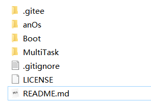
1. Open the RTOS_APP.uvmpw workspace under the MultiTask directory
2. Modify the macro PLL_M in the Boot/start/boot.c file of the osBOOT project according to the actual crystal oscillator frequency, then compile
3. Modify the hardware device configurations in the AnOs/Drv/DrvLed.c and DrvUart.c files, then compile
4. Set the osBoot, AnOs, App1, and App2 in the workspace as active projects, then download to the target board
5. Reset the target board, and the LED light will blink at a 2S cycle, while the serial port outputs the string “abc” at a 1s cycle.


If you think the article is good, click “Share”, “Like”, “View”!