1. Introduction
1.1 Project Development Background
With the continuous acceleration of urbanization, a large population is pouring into cities. Accompanying this is the rapid increase in the number of private cars, leading to a sharp rise in the demand for parking facilities, resulting in the continuous increase in the scale and number of parking lots. However, most traditional parking lots adopt a simple “always-on” mode or fixed schedule switch control for safety and management convenience. Regardless of the actual traffic and pedestrian flow, lights typically operate at full power 24/7 or for extended periods, leading to enormous electricity consumption, causing serious energy waste, and making it difficult to flexibly adjust lighting brightness according to actual needs, resulting in high operating costs.
At the same time, there are safety hazards in some dimly lit areas, affecting user experience. Therefore, developing an intelligent parking lot lighting system to achieve intelligent and energy-saving control of lighting is of significant practical importance.
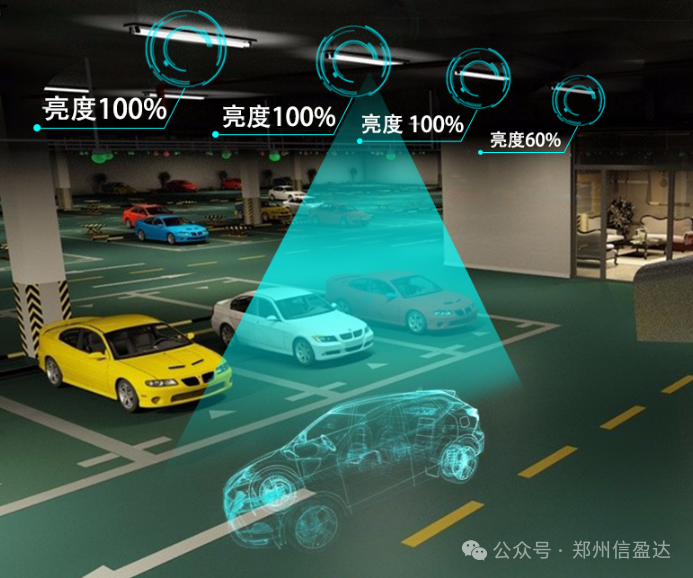
This project designs and implements an intelligent parking lot lighting system based on 5.8G radar detection and light-sensitive sensing, capable of real-time detection of vehicle/pedestrian movement and ambient light intensity, and driving LED lights to achieve precise dimming lighting on demand and by zone. This system is particularly suitable for underground garages, multi-story parking lots, and other scenarios requiring efficient energy saving and safety assurance, and can also serve as a teaching demonstration platform for IoT sensing and control technology. By deeply integrating high-sensitivity 5.8G radar, low-cost light-sensitive resistors, and efficient LED lights into an embedded control unit, our solution provides traditional parking lots with adaptive lighting upgrades of “lights on when people arrive, lights off when cars leave,” significantly reducing energy consumption and operating costs while enhancing safety and management efficiency.
1.2 Functions of the Design Implementation
(1) Vehicle Sensing Brightness Adjustment: Utilizing the 5.8G radar sensor to detect vehicle passage status, when no vehicle is detected, the LED lights operate at 30% brightness, maximizing energy savings while meeting basic lighting needs; when a vehicle is detected, the lights immediately switch to 100% brightness, providing sufficient illumination for safe driving.
(2) Lighting Fault Detection and Reporting: The system monitors the actual light intensity in the lighting area in real-time through the light sensor. When it detects extremely low or zero light intensity, the system determines that the lights in that area are damaged and immediately activates a reporting mechanism to transmit the fault information to the relevant management terminal for timely repair and replacement.
(3) Status Visualization Display: Utilizing a TFT LCD screen to display the operational status of the LED lights in real-time, where status 1 represents the lights at 100% brightness, status 2 represents the lights at 30% brightness, and status 3 represents the lights in a damaged state, allowing developers and managers to intuitively understand the working condition of the lights.
(4) Independent Key Interaction Control: Equipped with independent keys, providing manual operation interfaces for developers and managers, allowing for system parameter settings, status switching, and other operations via buttons, enhancing the system’s flexibility and operability, serving as an emergency control method when automatic control malfunctions.
1.3 Project Hardware Module Composition
(1) Main Control Chip: STM32F103RCT6
The STM32F103RCT6 is a microcontroller based on the ARM Cortex-M3 architecture, featuring powerful processing capabilities and a rich set of peripheral interfaces, suitable for the project’s real-time control and data processing needs. It is responsible for processing data collected from the radar and light-sensitive modules, timely controlling the brightness of the lights, displaying on the screen, and coordinating the correct operation of the entire system.
(2) 5.8G Radar Module: LD012
The LD012 module serves as the core component for vehicle and pedestrian detection, characterized by high detection accuracy, strong anti-interference capability, and a wide detection range. It can quickly and accurately sense the movement of objects within the monitored area, transmitting detection signals to the main control unit to trigger lighting control actions.
(3) Light-Sensitive Module: 5506
The light-sensitive resistor module is used to sense changes in ambient light intensity in real-time, converting light signals into electrical signals and transmitting them to the main control unit, providing environmental light data for adaptive lighting adjustment.
(4) LED Lights: HW-269
The lighting module uses the efficient and energy-saving LED light HW-269 as the light source, combined with a specially designed driving module, capable of precisely controlling the brightness and switching state of the lights according to the instructions from the main control unit, providing stable and high-quality lighting for the parking lot.
1.4 Design Concept
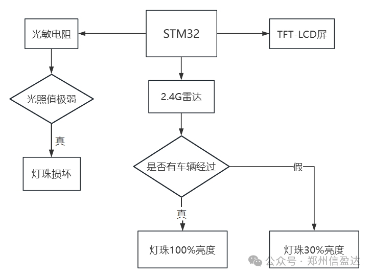
This project starts from the overall functional requirements of the system, focusing on vehicle sensing and lighting control, aiming to build an intelligent parking lot lighting system that can automatically adjust lighting brightness based on vehicle passage status, detect lighting faults, and achieve status visualization.
In terms of hardware selection, this project uses the STM32F103RCT6 as the core control unit, which has strong data processing capabilities and a rich set of peripheral interfaces, efficiently completing data collection from various sensors and executing control commands. To accurately detect vehicle passage status, a 5.8G radar sensor is selected, which responds quickly and detects accurately, capturing vehicle passage information in a timely manner. A light sensor is used to monitor the light intensity in the lighting area to determine whether the lights are damaged, providing strong support for fault detection due to its high sensitivity and reliable data.
After obtaining vehicle passage information and light intensity data, the main control unit is responsible for real-time processing and analysis of this data, adjusting the brightness of the lights through the light driver module. When the 5.8G radar sensor detects a vehicle passing, it controls the lights to switch to 100% brightness; when no vehicle is detected, it maintains the lights at 30% brightness. When the light sensor detects extremely low or zero light intensity, it determines that the lights are damaged and reports this. Finally, the TFT LCD screen displays the operational status of the lights, providing a more intuitive interface, and independent keys allow for interactive control.
1.5 Development Environment Introduction
The programming language for STM32 is generally chosen to be C, as C has high execution efficiency, and the executable files compiled from C are closest to machine code. Assembly language has the highest execution efficiency, but its portability is relatively poor. Currently, some low-end microcontrollers still use it in some operating system kernels, while regular microcontroller programming is mainly based on C.
This project’s device-side development uses the Keil uVision5 (Keil5) integrated development environment (IDE). Keil5 is a widely used development tool designed specifically for embedded system development, supporting various processor architectures, including the STM32 series microcontrollers. It provides an intuitive interface to help developers write, debug, and compile code, and has powerful debugging tools that facilitate step-by-step debugging and variable monitoring, making it very suitable for embedded software development.

1.6 Module Technical Details Introduction
(1) 5.8G Radar Module Technology
The 5.8G radar module uses electromagnetic waves in a specific frequency band for vehicle detection, employing the FMCW (Frequency Modulated Continuous Wave) principle to detect vehicles by transmitting and receiving signals. Its working process involves continuously emitting electromagnetic waves in a specific frequency band (5.8G) and receiving reflected signals. When a vehicle enters its detection area, the frequency of the reflected wave changes due to the Doppler effect. The radar module can accurately identify the vehicle’s passage status by precisely calculating the frequency difference between the transmitted and reflected waves.
(2) Light Sensor Module Technology
The light sensor can convert light intensity into corresponding electrical signals. We detect the magnitude of the electrical signal by configuring the ADC peripheral, which reflects the light intensity. The ADC can convert continuously varying analog signals into discrete digital signals. Its working principle involves sampling, quantifying, and encoding the analog electrical signal to convert the analog quantity into a digital quantity for processing by the main control unit.
In this system, a 12-bit resolution ADC is selected, sufficient to meet the precision requirements for light intensity detection. During the conversion process, the ADC compares the input analog voltage with a reference voltage using an internal comparator, iterating multiple times to obtain the corresponding digital value. When the light sensor detects changes in light intensity, the output electrical signal changes accordingly, and the ADC converts this electrical signal in real-time, transmitting the converted digital data to the main control unit, which uses this data to determine light intensity and thus ascertain whether the lights are damaged.
(3) LED Lights and Driver Module Technology
In this project, we use PWM (Pulse Width Modulation) technology to control the brightness of the lights. The core of PWM is to generate a series of pulse signals through the STM32’s peripheral timer, controlling the duty cycle of the pulses (the ratio of the duration of the high level to the entire pulse period) to adjust the average output voltage.
In the light driver, when the PWM signal’s duty cycle is 100%, the average voltage across the lights is at its highest, causing the lights to emit at 100% brightness; when the duty cycle is adjusted to 30%, the average voltage across the lights decreases, achieving a 30% brightness lighting effect. This method of precisely adjusting the duty cycle to control the brightness of the lights ensures stable lighting effects, avoiding flickering or unstable brightness. Additionally, during the PWM dimming process, the lights are either in full power operation or in low power state, with no intermediate inefficient working range, thus greatly improving energy utilization efficiency, aligning with the energy-saving design goals of the intelligent parking lot lighting system.
2. Hardware Selection and Hardware Connection Block Diagram
2.1 5.8G Radar LD012 Module
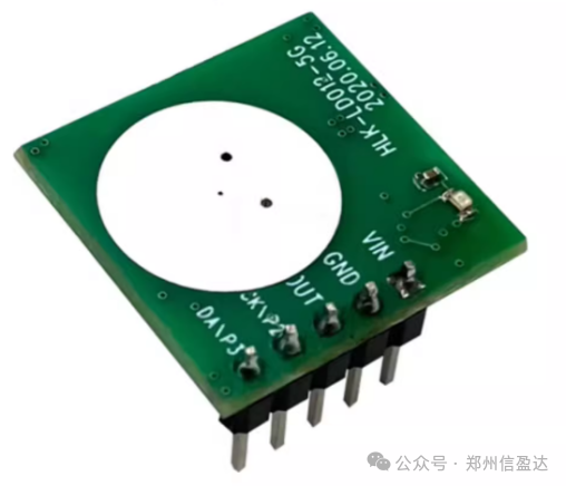
HLK-LD012-5G is an ultra-low power 5.8G radar sensor launched by Hailin Technology, with an overall power consumption of about 68uA and a compact size of 20mm*20mm. This module fully integrates a 5.8GHz microwave circuit, intermediate frequency amplification circuit, and signal processor, with high integration and good production consistency, paired with a miniaturized planar antenna, ensuring sensor performance while significantly reducing overall size. The module can be used in various scenarios for detecting human presence or moving targets.
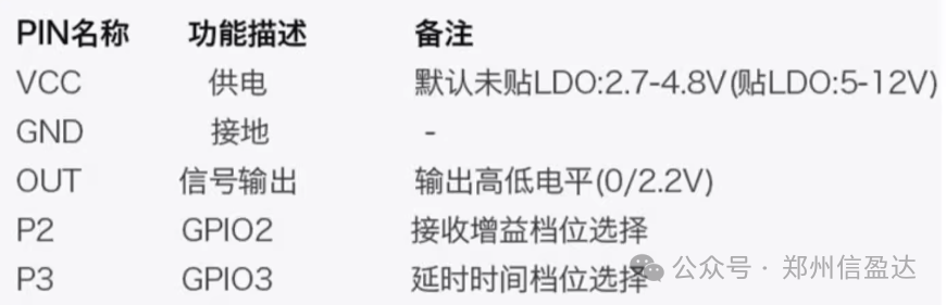
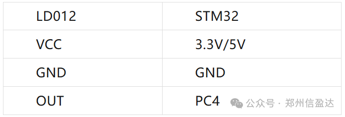
The module has five pins, and by default, only the VCC, GND, and OUT pins are used. If tuning distance and delay time parameters are needed, they can be selected through the P2 and P3 pins in floating or low state combined with specific resistors on the module, or by rewriting internal parameters using an external MCU reserved on the module. The following table defines the PIN pinout:
The LD012 module is connected to the microcontroller as follows:
 2.2 Light-Sensitive Resistor
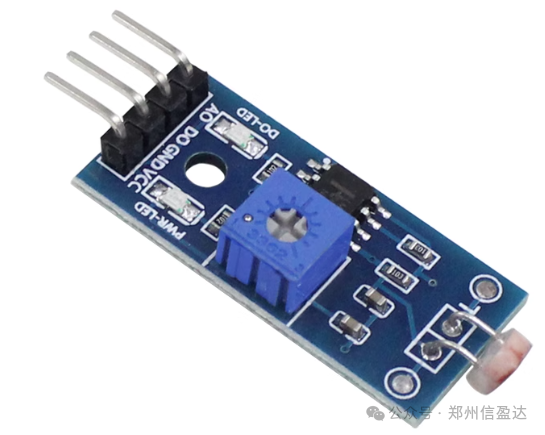
The light-sensitive resistor sensor uses a wide voltage LM393 comparator for comparison output, providing clean signals, good waveforms, and strong driving capability. It features an adjustable potentiometer to set the light brightness threshold for detection, supporting DO digital switch output (0 and 1) and AO analog voltage output. The module operates based on the internal photoelectric effect, where the resistance value rapidly decreases with increasing light intensity, allowing us to detect the brightness of our LED module and reflect whether it is damaged.
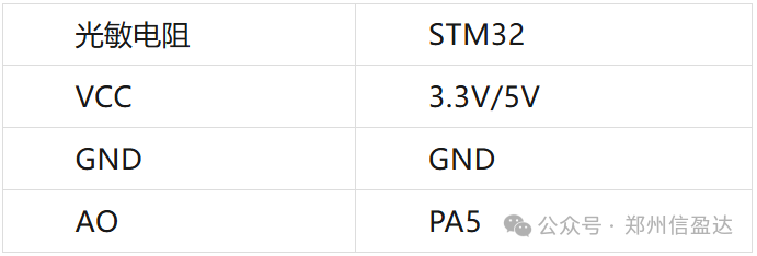
The module has four pins: power pin (VCC), ground pin (GND), digital output pin (DO), and analog output pin (AO). The module is connected to the microcontroller as shown in the following table:
2.3 LED Lights HW-269 Module
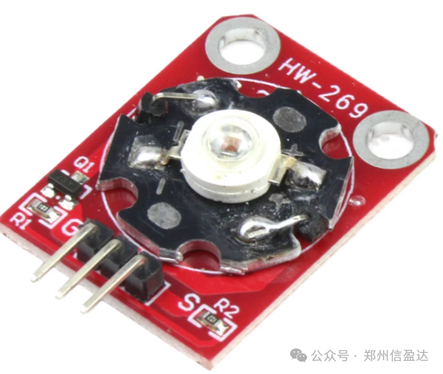
LED lights are characterized by high luminous efficiency, long lifespan, and low energy consumption, making them suitable as lighting sources for parking lots. The driver module uses PWM (Pulse Width Modulation) technology to control the brightness of the lights by adjusting the duty cycle of the pulse signals, allowing precise switching between 30% and 100% brightness, ensuring stable and energy-efficient lighting effects.
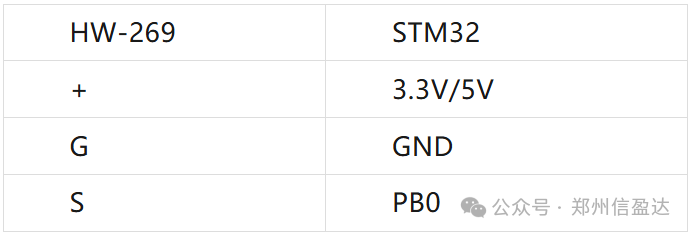
The HW-269 module has three pins: power pin (+), ground pin (G), and signal control pin (S). The module is connected to the microcontroller as shown in the following table:
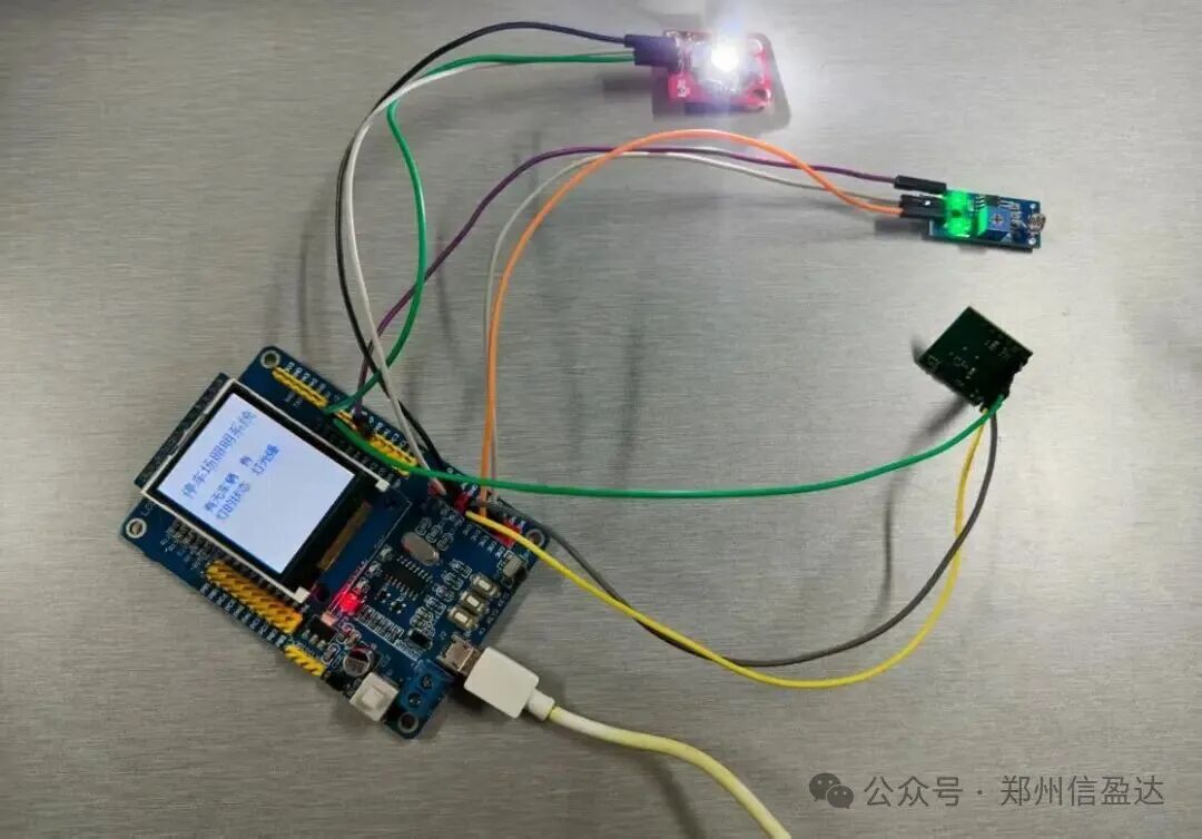
The final hardware connection diagram is shown below:
3. STM32 Code Design
3.1 Related Module Driver Code
(1) 5.8G Radar Module
void Radar_Config(void){ RCC_APB2PeriphClockCmd(RCC_APB2Periph_GPIOC,ENABLE); GPIO_InitTypeDef GPIO_InitStructure = {0}; GPIO_InitStructure.GPIO_Mode = GPIO_Mode_IN_FLOATING; GPIO_InitStructure.GPIO_Pin = GPIO_Pin_4; //PC4 GPIO_Init(GPIOC,&GPIO_InitStructure);}(2) Light-Sensitive Resistor
void Light_Config(void){ //1.GPIO initialization GPIO_InitTypeDef GPIO_InitStruct = {0}; RCC_APB2PeriphClockCmd(RCC_APB2Periph_GPIOA,ENABLE); GPIO_InitStruct.GPIO_Mode = GPIO_Mode_AIN; GPIO_InitStruct.GPIO_Pin = GPIO_Pin_5; GPIO_Init(GPIOA,&GPIO_InitStruct); //2.Configure ADC clock-->6 division 12MHZ RCC_ADCCLKConfig(RCC_PCLK2_Div6); RCC_APB2PeriphClockCmd(RCC_APB2Periph_ADC2,ENABLE); //3.ADC configuration ADC_InitTypeDef ADC_InitStructure = {0}; //ADC mode independent mode ADC_InitStructure.ADC_Mode = ADC_Mode_Independent; //Scan mode ENABLE single mode DISABLE ADC_InitStructure.ADC_ScanConvMode = DISABLE; //Continuous mode ENABLE single mode DISABLE ADC_InitStructure.ADC_ContinuousConvMode = DISABLE; ADC_InitStructure.ADC_ExternalTrigConv = ADC_ExternalTrigConv_None; ADC_InitStructure.ADC_DataAlign = ADC_DataAlign_Right; ADC_InitStructure.ADC_NbrOfChannel = 1; //ADC initialization ADC_Init(ADC2, &ADC_InitStructure); //Regular channel configuration //Channel 11 regular sequence 1 55.5 sampling cycles ADC_RegularChannelConfig(ADC2, ADC_Channel_5, 1, ADC_SampleTime_55Cycles5); //Enable ADC ADC_Cmd(ADC2, ENABLE); //Initialize calibration register ADC_ResetCalibration(ADC2); //Wait for calibration register initialization to complete while(ADC_GetResetCalibrationStatus(ADC2)); //Start calibration ADC_StartCalibration(ADC2); //Wait for calibration to complete while(ADC_GetCalibrationStatus(ADC2));}(3) LED Lights
void HW269_Config(void){ GPIO_InitTypeDef GPIO_InitStructure = {0}; RCC_APB2PeriphClockCmd(RCC_APB2Periph_GPIOB,ENABLE); GPIO_InitStructure.GPIO_Mode = GPIO_Mode_AF_PP; GPIO_InitStructure.GPIO_Speed = GPIO_Speed_50MHz; GPIO_InitStructure.GPIO_Pin = GPIO_Pin_0; GPIO_Init(GPIOB,&GPIO_InitStructure); TIM_TimeBaseInitTypeDef TIM_BaseInitStructure = {0}; TIM_OCInitTypeDef TIM_OCInitStructure = {0}; RCC_APB1PeriphClockCmd(RCC_APB1Periph_TIM3, ENABLE); TIM_BaseInitStructure.TIM_ClockDivision = TIM_CKD_DIV1; TIM_BaseInitStructure.TIM_CounterMode = TIM_CounterMode_Up; //Up counting TIM_BaseInitStructure.TIM_Period = 999; //Reload value TIM_BaseInitStructure.TIM_Prescaler = 71; //Internal auto increment of the prescaler TIM_TimeBaseInit(TIM3, &TIM_BaseInitStructure); TIM_ARRPreloadConfig(TIM3, ENABLE);//ARR preload enable //Output compare configuration TIM_OCInitStructure.TIM_OCMode = TIM_OCMode_PWM1; TIM_OCInitStructure.TIM_OCPolarity = TIM_OCPolarity_High; TIM_OCInitStructure.TIM_OutputState = TIM_OutputState_Enable; TIM_OCInitStructure.TIM_Pulse = 0; TIM_OC3Init(TIM3, &TIM_OCInitStructure); TIM_OC3PreloadConfig(TIM3, ENABLE);//CCR preload enable TIM_Cmd(TIM3, ENABLE); //Enable timer HW269_OFF;}3.2 Main Function Framework Code
int main(){ JTAG_SWD_Config();//Disable JTAG function, enable SWD function SysTick_Config(72000);//Timer initialization NVIC_SetPriorityGrouping(5);//Interrupt priority grouping USART1_Config(115200);//Serial port initialization Key_Config(); Led_Config(); HW269_Config();//LED initialization Beep_Config(); Light_Config();//Light-sensitive resistor Radar_Config();//Radar detection LCD_Init();//LCD initialization LCD_Fill(0,0,128,160,WHITE); LCD_ShowChinese(10,20,(u8 *)"Parking Lot Lighting System",BLUE,WHITE,16,1); LCD_ShowChinese(10,50,(u8 *)"Vehicle Presence",BLUE,WHITE,12,1); LCD_ShowChinese(10,66,(u8 *)"Light Status",BLUE,WHITE,12,1); while(1) { if(device_time > 30) { if(radar == 1) { printf("Vehicle detected\r\n"); LCD_ShowChinese(70,50,(u8 *)"Yes",BLUE,WHITE,12,0); HW265(1000);//100% } else { printf("No vehicle detected\r\n"); LCD_ShowChinese(70,50,(u8 *)"No",BLUE,WHITE,12,0); HW265(300);//30% } device_time = 0; } //Light detection if(light_time > 200) { value = Get_Adc_Average(10); printf("light:%d\r\n",value); light_time = 0; } //Light level judgment if(value >= 1500) { LCD_ShowChinese(70,66,(u8 *)"Bright",BLUE,WHITE,12,0); } else if(value<1500&&value>=100) { LCD_ShowChinese(70,66,(u8 *)"Dim",BLUE,WHITE,12,0); } else if(value < 100) { LCD_ShowChinese(70,66,(u8 *)"Light Damaged",BLUE,WHITE,12,0); } }}3.3 Key Code Explanation
1. System Initialization: Includes STM32 hardware initialization, GPIO initialization, radar module, light-sensitive module, LED, and screen module initialization.
2. Sensor Data Reading: Periodically reads vehicle detection data from the 5.8G radar module and light intensity data from the light sensor, providing a basis for the main control logic judgment.
3. LED Status Control: Based on radar data, determines whether a vehicle has passed, controlling the LED to switch between 30% and 100% brightness; combined with light sensor data, if the LED is determined to be damaged, it triggers the reporting mechanism.
4. LCD Screen Real-Time Display: Displays the current status of the LED (bright, dim, damaged) and vehicle presence status on the screen in real-time for easy viewing by personnel.
4. Conclusion
This system is based on the STM32F103RCT6 microcontroller, successfully constructing a complete intelligent parking lot lighting system. By accurately detecting vehicle passage status with the 5.8G radar sensor, combined with the PWM brightness control of the LED driver module (switching between 30% and 100% brightness), it achieves an intelligent lighting process of “100% brightness when vehicles pass, 30% brightness when no vehicles are present”; utilizing the light sensor to monitor light intensity, it completes the judgment and reporting of LED damage status. Meanwhile, the 1.8-inch TFT LCD screen displays the three states of the LED (bright, dim, damaged) in real-time, and independent keys provide manual interaction, forming a closed-loop intelligent lighting management system.
This project not only demonstrates the application of embedded technology and intelligent sensors but also designs functional modules tailored to the actual needs of parking lot lighting through in-depth research. The successful implementation of the project can effectively reduce energy consumption for parking lot lighting and enhance lighting management efficiency, possessing strong practical value, while also providing a reference example for the development of intelligent parking lot auxiliary systems. In the future, with continuous technological advancements, this project can further expand its functionalities, such as optimizing vehicle detection accuracy with artificial intelligence algorithms, automatically adjusting brightness switching delay times based on parking lot traffic flow, and enhancing the anti-interference capability of light sensors in complex environments, making it a more comprehensive and adaptable intelligent lighting tool for diverse parking lot needs.