Last year, the product developed by the company utilized CAN, and it is still in use now. I would like to recall and organize the previous work for future reference.First, let me present the circuit diagram.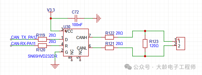
1. Header File (can_driver.h)
#ifndef __CAN_DRIVER_H
#define __CAN_DRIVER_H
#include "stm32f10x.h"
// CAN frame type definition
typedef enum {
    CAN_FRAME_STD = 0,  // Standard frame (11-bit ID)
    CAN_FRAME_EXT       // Extended frame (29-bit ID)
} CAN_FrameTypeDef;
// CAN transmit data structure
typedef struct {
    CAN_FrameTypeDef FrameType;  // Frame type
    uint32_t ID;                 // Frame ID (only low 11 bits valid for standard frame, low 29 bits valid for extended frame)
    uint8_t DataLen;             // Data length (0~8 bytes)
    uint8_t Data[8];             // Data content
} CAN_TxMsgTypeDef;
// CAN receive data structure
typedef struct {
    CAN_FrameTypeDef FrameType;  // Frame type
    uint32_t ID;                 // Received frame ID
    uint8_t DataLen;             // Data length
    uint8_t Data[8];             // Received data
} CAN_RxMsgTypeDef;
// Function declarations
void CAN_InitConfig(void);                                  // CAN initialization
uint8_t CAN_SendData(CAN_TxMsgTypeDef *txMsg);              // CAN send data
void CAN_ReceiveData(CAN_RxMsgTypeDef *rxMsg);              // Read receive buffer
uint8_t CAN_CheckReceive(void);                             // Check if there is received data
#endif  // __CAN_DRIVER_H
2. Source File (can_driver.c)
#include "can_driver.h"
#include "stm32f10x_gpio.h"
#include "stm32f10x_can.h"
#include "stm32f10x_rcc.h"
// Receive buffer (circular buffer, size can be adjusted as needed)
#define CAN_RX_BUF_SIZE 16
static CAN_RxMsgTypeDef CAN_RxBuf[CAN_RX_BUF_SIZE];
static uint8_t CAN_RxHead = 0;
static uint8_t CAN_RxTail = 0;
/**
 * @brief  CAN pin initialization (PA11=CAN_RX, PA12=CAN_TX)
 */
static void CAN_GPIO_Init(void) {
    GPIO_InitTypeDef GPIO_InitStruct;
    // Enable GPIOA and CAN1 clock
    RCC_APB2PeriphClockCmd(RCC_APB2Periph_GPIOA, ENABLE);
    RCC_APB1PeriphClockCmd(RCC_APB1Periph_CAN1, ENABLE);
    // Configure PA11 (CAN_RX) as floating input
    GPIO_InitStruct.GPIO_Pin = GPIO_Pin_11;
    GPIO_InitStruct.GPIO_Mode = GPIO_Mode_IPU;  // Pull-up input (enhanced anti-interference)
    GPIO_InitStruct.GPIO_Speed = GPIO_Speed_50MHz;
    GPIO_Init(GPIOA, &GPIO_InitStruct);
    // Configure PA12 (CAN_TX) as alternate push-pull output
    GPIO_InitStruct.GPIO_Pin = GPIO_Pin_12;
    GPIO_InitStruct.GPIO_Mode = GPIO_Mode_AF_PP;  // Alternate push-pull
    GPIO_InitStruct.GPIO_Speed = GPIO_Speed_50MHz;
    GPIO_Init(GPIOA, &GPIO_InitStruct);
}
/**
 * @brief  CAN interrupt initialization (receive interrupt)
 */
static void CAN_NVIC_Init(void) {
    NVIC_InitTypeDef NVIC_InitStruct;
    // Enable CAN1 RX0 interrupt (receive FIFO0 full interrupt)
    NVIC_InitStruct.NVIC_IRQChannel = CAN1_RX0_IRQn;
    NVIC_InitStruct.NVIC_IRQChannelPreemptionPriority = 1;  // Preemption priority
    NVIC_InitStruct.NVIC_IRQChannelSubPriority = 0;         // Response priority
    NVIC_InitStruct.NVIC_IRQChannelCmd = ENABLE;
    NVIC_Init(&NVIC_InitStruct);
}
/**
 * @brief  CAN initialization configuration (baud rate 500Kbps, clock APB1=36MHz)
 * @note   Baud rate calculation: CAN_BRP = (APB1 clock / (18 * baud rate)) - 1
 *         Example: 36MHz / (18 * 500Kbps) = 4 → BRP=3 (need to subtract 1)
 */
void CAN_InitConfig(void) {
    CAN_InitTypeDef CAN_InitStruct;
    CAN_FilterInitTypeDef CAN_FilterInitStruct;
    CAN_GPIO_Init();   // Pin initialization
    CAN_NVIC_Init();   // Interrupt initialization
    // CAN mode configuration
    CAN_InitStruct.CAN_TTCM = DISABLE;          // Disable time-triggered communication mode
    CAN_InitStruct.CAN_ABOM = ENABLE;           // Automatic offline management (automatically recover after exception)
    CAN_InitStruct.CAN_AWUM = ENABLE;           // Automatic wake-up mode (automatically wake up after sleep)
    CAN_InitStruct.CAN_NART = DISABLE;          // Enable automatic retransmission (retransmit after send failure)
    CAN_InitStruct.CAN_RFLM = DISABLE;          // Receive FIFO non-locking mode (overwrite old data when full)
    CAN_InitStruct.CAN_TXFP = DISABLE;          // Send priority determined by ID
    CAN_InitStruct.CAN_Mode = CAN_Mode_Normal;  // Normal operation mode (not loopback)
    // CAN_InitStruct.CAN_Mode = CAN_Mode_LoopBack; // Loopback mode (for self-test)
    // Baud rate configuration (500Kbps)
    CAN_InitStruct.CAN_SJW = CAN_SJW_1tq;       // Synchronization jump width: 1 time quantum
    CAN_InitStruct.CAN_BS1 = CAN_BS1_8tq;       // Time segment 1: 8 time quanta
    CAN_InitStruct.CAN_BS2 = CAN_BS2_9tq;       // Time segment 2: 9 time quanta
    CAN_InitStruct.CAN_Prescaler = 3;           // Prescaler (BRP=3 → baud rate 500Kbps)
    CAN_Init(CAN1, &CAN_InitStruct);    // CAN filter configuration (default to receive all IDs, can be modified as needed)
    CAN_FilterInitStruct.CAN_FilterNumber = 0;                  // Filter 0
    CAN_FilterInitStruct.CAN_FilterMode = CAN_FilterMode_IdMask; // Mask mode
    CAN_FilterInitStruct.CAN_FilterScale = CAN_FilterScale_32bit; // 32-bit filter
    CAN_FilterInitStruct.CAN_FilterIdHigh = 0x0000;             // Filter ID high 16 bits (all 0)
    CAN_FilterInitStruct.CAN_FilterIdLow = 0x0000;              // Filter ID low 16 bits (all 0)
    CAN_FilterInitStruct.CAN_FilterMaskIdHigh = 0x0000;         // Mask high 16 bits (all 0 → no filtering)
    CAN_FilterInitStruct.CAN_FilterMaskIdLow = 0x0000;          // Mask low 16 bits (all 0 → no filtering)
    CAN_FilterInitStruct.CAN_FilterFIFOAssignment = CAN_Filter_FIFO0; // Store in FIFO0 after matching
    CAN_FilterInitStruct.CAN_FilterActivation = ENABLE;         // Enable filter
    CAN_FilterInit(&CAN_FilterInitStruct);    // Enable CAN1 RX0 interrupt (FIFO0 full interrupt)
    CAN_ITConfig(CAN1, CAN_IT_FMP0, ENABLE);
}
/**
 * @brief  CAN send data
 * @param  txMsg: Transmit data structure (frame type, ID, data length, data)
 * @retval 0: Send success; 1: Send failure (mailbox full)
 */
uint8_t CAN_SendData(CAN_TxMsgTypeDef *txMsg) {
    CAN_TxMailBox_TypeDef txMailBox;
    CAN_TxHeaderTypeDef txHeader;
    // Check data length validity
    if (txMsg->DataLen > 8) return 1;
    // Configure send frame header
    txHeader.StdId = (txMsg->FrameType == CAN_FRAME_STD) ? (txMsg->ID & 0x7FF) : 0; // Standard ID (11 bits)
    txHeader.ExtId = (txMsg->FrameType == CAN_FRAME_EXT) ? (txMsg->ID & 0x1FFFFFFF) : 0; // Extended ID (29 bits)
    txHeader.RTR = CAN_RTR_Data;  // Data frame (not remote frame)
    txHeader.IDE = (txMsg->FrameType == CAN_FRAME_EXT) ? CAN_ID_EXT : CAN_ID_STD; // Frame type
    txHeader.DLC = txMsg->DataLen; // Data length
    txHeader.TransmitGlobalTime = DISABLE; // Do not include send timestamp
    // Wait for send mailbox to be free, timeout 10ms
    uint32_t timeout = 10000;
    while ((CAN_GetTxMailboxesFreeLevel(CAN1) == 0) && (timeout-- > 0));
    if (timeout == 0) return 1;
    // Send data
    txMailBox = CAN_AddTxMessage(CAN1, &txHeader, txMsg->Data, NULL);
    // Wait for send completion (optional, depending on whether blocking is needed)
    timeout = 10000;
    while ((CAN_GetTxStatus(CAN1, txMailBox) == CAN_TxStatus_Pending) && (timeout-- > 0));
    if (timeout == 0) return 1;
    return 0;
}
/**
 * @brief  Read data from receive buffer
 * @param  rxMsg: Receive data structure (output parameter)
 * @retval None */
void CAN_ReceiveData(CAN_RxMsgTypeDef *rxMsg) {
    if (CAN_RxHead == CAN_RxTail) return; // No data
    // Read circular buffer
    *rxMsg = CAN_RxBuf[CAN_RxTail];
    CAN_RxTail = (CAN_RxTail + 1) % CAN_RX_BUF_SIZE;
}
/**
 * @brief  Check if there is received data
 * @retval 1: There is data; 0: No data */
uint8_t CAN_CheckReceive(void) {
    return (CAN_RxHead != CAN_RxTail) ? 1 : 0;
}
/**
 * @brief  CAN1 RX0 interrupt service function (receive FIFO0 full interrupt)
 */
void CAN1_RX0_IRQHandler(void) {
    CAN_RxHeaderTypeDef rxHeader;
    uint8_t rxData[8];
    // Read receive frame header and data
    if (CAN_GetRxMessage(CAN1, CAN_RX_FIFO0, &rxHeader, rxData) == SUCCESS) {
        // Fill receive structure
        CAN_RxMsgTypeDef rxMsg;
        rxMsg.FrameType = (rxHeader.IDE == CAN_ID_EXT) ? CAN_FRAME_EXT : CAN_FRAME_STD;
        rxMsg.ID = (rxMsg.FrameType == CAN_FRAME_EXT) ? rxHeader.ExtId : rxHeader.StdId;
        rxMsg.DataLen = rxHeader.DLC;
        memcpy(rxMsg.Data, rxData, rxHeader.DLC);
        // Store in circular buffer (to avoid overflow)
        uint8_t nextHead = (CAN_RxHead + 1) % CAN_RX_BUF_SIZE;
        if (nextHead != CAN_RxTail) {
            CAN_RxBuf[CAN_RxHead] = rxMsg;
            CAN_RxHead = nextHead;
        }
    }
    // Clear interrupt flag
    CAN_ClearITPendingBit(CAN1, CAN_IT_FMP0);
}
3. Usage Instructions
1. Initialization
Call the CAN initialization function in <span>main.c</span>:
#include "can_driver.h"
int main(void) {
    // System initialization (clock, NVIC, etc., according to your project configuration)
    SystemInit();
    CAN_InitConfig();  // Initialize CAN peripheral
    while (1) {
        // Business logic
    }
}
2. Example of Sending Data, add the following code in the main program for testing, or write it as a function
// Example of sending standard frame (ID=0x123, data=0x01,0x02,0x03)
CAN_TxMsgTypeDef txMsg;
txMsg.FrameType = CAN_FRAME_STD;
txMsg.ID = 0x123;
txMsg.DataLen = 3;
txMsg.Data[0] = 0x01;
txMsg.Data[1] = 0x02;
txMsg.Data[2] = 0x03;
if (CAN_SendData(&txMsg) == 0) {
    // Send success
} else {
    // Send failure
}
// Example of sending extended frame (ID=0x12345678, data=0xAA,0xBB)
txMsg.FrameType = CAN_FRAME_EXT;
txMsg.ID = 0x12345678;
txMsg.DataLen = 2;
txMsg.Data[0] = 0xAA;
txMsg.Data[1] = 0xBB;
CAN_SendData(&txMsg);
3. Example of Receiving Data
In the <span>main</span> function’s infinite loop, check and read received data:
while (1) {
    CAN_RxMsgTypeDef rxMsg;
    if (CAN_CheckReceive() == 1) {  // Check if there is received data
        CAN_ReceiveData(&rxMsg);    // Read data
        // Process received data (example: print ID and data)
        if (rxMsg.FrameType == CAN_FRAME_STD) {
            printf("Standard Frame ID: 0x%X, Length: %d, Data: ", rxMsg.ID, rxMsg.DataLen);
        } else {
            printf("Extended Frame ID: 0x%X, Length: %d, Data: ", rxMsg.ID, rxMsg.DataLen);
        }
        for (uint8_t i=0; i<rxMsg.DataLen; i++) {
            printf("%02X ", rxMsg.Data[i]);
        }
        printf("\r\n");
    }
}
4. Key Parameter Adjustments
-
Modifying Baud Rate:
- Baud rate calculation formula:
<span>Baud Rate = APB1 Clock / ( (SJW + BS1 + BS2) * BRP )</span> - Example: APB1=36MHz, need to configure 250Kbps baud rate:
CAN_InitStruct.CAN_SJW = CAN_SJW_1tq;
CAN_InitStruct.CAN_BS1 = CAN_BS1_8tq;
CAN_InitStruct.CAN_BS2 = CAN_BS2_9tq;
CAN_InitStruct.CAN_Prescaler = 7;  // 36MHz / (18 * 250Kbps) = 8 → BRP=7
2. Filter Configuration:
- If you need to filter specific IDs, modify the filter ID and mask:
// Only receive data with standard frame ID=0x123
CAN_FilterInitStruct.CAN_FilterIdHigh = (0x123 << 5) & 0xFFFF;  // Standard ID shifted left by 5 bits (to fit 32-bit filter format)
CAN_FilterInitStruct.CAN_FilterIdLow = 0x0000;
CAN_FilterInitStruct.CAN_FilterMaskIdHigh = 0x7FF << 5;  // Mask all 1s (strict match)
CAN_FilterInitStruct.CAN_FilterMaskIdLow = 0x0000;
3. Interrupt Configuration:If you need to disable interrupts, remove the <span>CAN_NVIC_Init()</span> call, and switch to polling mode for receiving:
// Polling mode receive example
if (CAN_MessagePending(CAN1, CAN_RX_FIFO0) > 0) {
    CAN_GetRxMessage(CAN1, CAN_RX_FIFO0, &rxHeader, rxData);
    // Data processing...
}
5. Precautions
- Ensure the APB1 clock configuration is correct (maximum APB1 clock for STM32F103 is 36MHz).
- A CAN transceiver must be used (I used SN65HVD232), otherwise communication with the CAN bus will not be possible.
- Termination resistors: 120Ω termination resistors must be connected at both ends of the CAN bus (to match bus impedance).
- Loopback mode: During debugging, you can enable
<span>CAN_Mode_LoopBack</span><span> mode for self-transmission and reception without external hardware.</span> - Data length: The length of a CAN data frame is 0~8 bytes; exceeding this will cause send failure.
This driver is suitable for the STM32F103 series; other series (such as F4, L4) can refer to modify pin configurations, clock parameters, and register definitions (core logic remains consistent).