1.PWM Introduction
PWM (Pulse Width Modulation—— Pulse Width Modulation) is a very effective technique for controlling analog circuits using the digital output of microprocessors, widely used in measurement, communication, power control, and conversion in many fields.
PWM technology has an important concept called Duty Cycle(Duty Cycle), which is the percentage of the high level in the entire signal period within one cycle.PWM signals are periodic square wave signals with variable duty cycles.
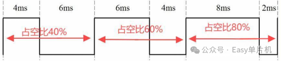
PWM is a typical application of timer output. In addition to basic timers, other timers can also generatePWM signal outputs. General timers can generate4 channels ofPWM, while advanced timers can generate up to7 channels ofPWM.
For example, each general timer has4 channels ofPWM output channels:TIMx_CH1, TIMx_CH2, TIMx_CH3, TIMx_CH4. Each channel corresponds to a capture/compare register:TIMx_CCR1, TIMx_CCR2, TIMx_CCR3, TIMx_CCR4.
2.PWM Implementation Principle
The value of the counterCNT is compared with the value of the capture/compare registerTIMx_CCRx, and based on the comparison result, the output level is determined, thus achievingPWM signal output.
Now assume the timer counting mode is counting up, the value of the timer automatic reload registerTIMx_ARR isARR, and the value of the capture/compare registerTIMx_CCRx isCCRx.
The counterCNT counts from0 to the automatic reload valueARR, and then starts counting from0, so the value of the automatic reload registerTIMx_ARR determines the period of thePWM signal.
Assuming the counter value is less thanCCRx value, the output is low; when the counter value is greater thanCCRx value, the output is high.The output effect of thePWM signal is shown in the figure below.
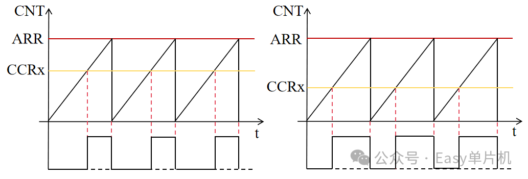
From the comparison in the above figure, it can be seen that with differentCCRx values, the duty cycle of thePWM signal also varies, meaning that theCCRx value determines the duty cycle of thePWM signal.
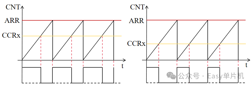
Of course, it can also be set so that when the counter value is less thanCCRx value, the output is high, and when the counter value is greater thanCCRx value, the output is low. The effect is shown in the figure below.
3.PWM Output Channel Structure
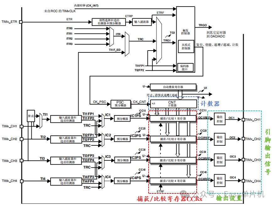
The value of the counterCNT is compared with the value of the capture/compare registerCCRx, and based on the comparison result, thePWM signal is output through the pin. The output level (high or low) based on the comparison result needs to be set through the relevant registers. The specific output channel settings are shown in the figure below.
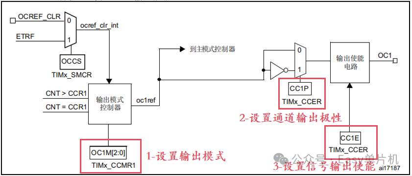
(1)TIMx_CCMR1 register’s OC1M[2:0] bits, set the output mode
110:PWM Mode 1
When counting up, onceTIMx_CNT < TIMx_CCR1, channel1 is at valid level, otherwise it is at invalid level; when counting down, onceTIMx_CNT > TIMx_CCR1, channel1 is at invalid level, otherwise it is at valid level.
111:PWM Mode 2
When counting up, onceTIMx_CNT < TIMx_CCR1, channel1 is at invalid level, otherwise it is at valid level; when counting down, onceTIMx_CNT > TIMx_CCR1, channel1 is at valid level, otherwise it is at invalid level.
(2) Set channel output polarity
0: High level valid
1: Low level valid
(3) Enable output signal, whether the signal can be output to the corresponding pin
0: Disable
1: Enable
【Example Explanation】(1)Counting up,PWM Mode 1, low level valid;
(2)Counting up,PWM Mode 2, high level valid;
The output effects of the two methods are shown in the figure below.
3.PWM Related Library Functions
1、PWM Output Initialization Library Function
Function Prototype:
void TIM_OCxInit(TIM_TypeDef* TIMx, TIM_OCInitTypeDef* TIM_OCInitStruct);(x=1,2,3,4)
Function Parameters:
TIMx:TIM1~TIM5,TIM8~TIM14
TIM_OCInitStruct: Structure pointer
typedef struct
{
uint16_t TIM_OCMode; // PWM Mode,PWM Mode 1 or PWM Mode 2
uint16_t TIM_OutputState; // Set compare output enable/ disable
uint16_t TIM_OutputNState; // This parameter is only used for advanced timers
uint16_t TIM_Pulse; // Value written to the capture compare register, 0x00~0xFF
uint16_t TIM_OCPolarity; // Compare output polarity
uint16_t TIM_OCNPolarity; // This parameter is only used for advanced timers
uint16_t TIM_OCIdleState; // This parameter is only used for advanced timers
uint16_t TIM_OCNIdleState; // This parameter is only used for advanced timers
} TIM_OCInitTypeDef;
1)TIM_OCMode:
TIM_OCMode_PWM1:PWM Mode 1
TIM_OCMode_PWM2:PWM Mode 2
2)TIM_OutputState:
TIM_OutputState_Enable: Compare output enable
TIM_OutputState_Disable: Compare output disable
3)TIM_OCPolarity:
TIM_OCPolarity_High: High level valid
TIM_OCPolarity_Low: Low level valid
Usage Example:
TIM_OCInitTypeDef TIM_OCInitStructure;// Define structure
TIM_OCInitStructure.TIM_OCMode = TIM_OCMode_PWM1; //PWM Mode 1
TIM_OCInitStructure.TIM_OutputState = TIM_OutputState_Enable; // Enable compare outputTIM_OCInitStructure. TIM_Pulse=0;// Compare value
TIM_OCInitStructure.TIM_OCPolarity = TIM_OCPolarity_High; // High level output polarity
TIM_OC2Init(TIM3, &TIM_OCInitStructure); // InitializeTIM3 Compare output channel 2
2、 Set Compare Value Library Function, External Change TIM_Pulse Value, i.e., Change CCR Value
Function Prototype::
void TIM_SetComparex(TIM_TypeDef* TIMx, uint16_t Compare); (x=1,2,3,4)
Function Parameters:
TIMx:TTIM1~TIM5,TIM8~TIM14
Compare: Value range0x00~0xFF
Usage Example: Example:TIM_SetCompare1(TIM2,1000);// Timer 2 Channel 1, Set Compare Value 100
3、 Enable Preload Register Library Function
Function Prototype::
void TIM_OCxPreloadConfig(TIM_TypeDef* TIMx, uint16_t TIM_OCPreload);(x=1,2,3,4)
Usage Example: Example:TIM_OC1PreloadConfig(TIM2, TIM_OCPreload_Enable);// Enable Timer 2 Channel 1 Preload Register
4、 Enable Automatic Reload Register Library Function
Function Prototype::
void TIM_ARRPreloadConfig(TIM_TypeDef* TIMx, FunctionalState NewState);
Usage Example: Example:TIM_ARRPreloadConfig(TIM2,ENABLE);
【Note】 In PWM applications, we often need to change the duty cycle (CCRx register) and period (ARR register) at runtime. If we directly write to these registers, the new values will take effect immediately, which may cause abnormal current output signals. To avoid this situation, we need to use the mechanism of preload registers and shadow registers. The new values will take effect in the next cycle.
5.PWM Usage Steps
1、 Enable timer clock and GPIO port clock
2、 Configure PWM pins, select pins, modes, etc.
3、 Configure the timing unit, set reload value, prescaler value, counting mode, etc.
4、 Configure the compare output structure, callTIM_OCxInit(TIMx,&TIM_OCInitStruct) function to complete initialization
5、 Enable preload register
TIM_OCxPreloadConfig(TIMx, TIM_OCPreload_Enable);
6、 Enable automatic reload register
7、TIM_ARRPreloadConfig(TIMx, ENABLE);
8、 Enable timerTIM_Cmd(TIMx,ENABLE);
9、 Continuously change the compare value CCRx, to achieve different duty cycle effects
TIM_SetComparex(TIMx,Compare);
Example Code: Taking Timer 14, Output Channel 1 as an example, corresponding pin PF9
void TIM14_PWM_Init(){GPIO_InitTypeDef GPIO_InitStruct; //GPIO port structureTIM_TimeBaseInitTypeDef TIM_TimeBaseStruct;// Timing structureTIM_OCInitTypeDef TIM_OCInitStruct;// Compare output structure/*1-Enable timer and GPIO port clock*/RCC_APB1PeriphClockCmd(RCC_APB1Periph_TIM14, ENABLE);RCC_AHB1PeriphClockCmd(RCC_AHB1Periph_GPIOF,ENABLE); /*2-Configure timer input pin*/GPIO_PinAFConfig(GPIOF,GPIO_PinSource9,GPIO_AF_TIM14);// Multiplexing function configurationGPIO_InitStruct.GPIO_Pin = GPIO_Pin_9; // Select pin A2GPIO_InitStruct.GPIO_Mode = GPIO_Mode_AF; // Multiplexing function modeGPIO_InitStruct.GPIO_Speed = GPIO_Speed_100MHz; // Output speedGPIO_InitStruct.GPIO_OType = GPIO_OType_PP; // Push-pull outputGPIO_InitStruct.GPIO_PuPd = GPIO_PuPd_UP; // GPIO_Init(GPIOF, &GPIO_InitStruct); /*3-Timing configuration*/TIM_TimeBaseStruct.TIM_Period = 1000-1;// Automatic reload ARR value TIM_TimeBaseStruct.TIM_Prescaler = 84-1;// Prescaler PSC value 10KHzTIM_TimeBaseStruct.TIM_ClockDivision=TIM_CKD_DIV1;// 1 prescalerTIM_TimeBaseStruct.TIM_CounterMode = TIM_CounterMode_Up;// Counting up modeTIM_TimeBaseInit(TIM14, &TIM_TimeBaseStruct);// Complete initialization/*4-Compare output configuration*/TIM_OCInitStruct.TIM_OCMode = TIM_OCMode_PWM2; // PWM Mode 1TIM_OCInitStruct.TIM_OutputState = TIM_OutputState_Enable; // Compare output enableTIM_OCInitStruct.TIM_OCPolarity = TIM_OCPolarity_High; // High level output polarity TIM_OC1Init(TIM14, &TIM_OCInitStruct); // Initialize TIM5 compare output channel 3/*5-Enable preload register*/TIM_OC1PreloadConfig(TIM14, TIM_OCPreload_Enable);/*6-Enable automatic reload register*/TIM_ARRPreloadConfig(TIM14, ENABLE);/*7-Enable timer*/TIM_Cmd(TIM14,ENABLE);}6.PWM Application: Breathing Light (LED light on the development board connected to PF9, PWM channel 1)
Main Function
#include "stm32f4xx.h"void delay_ms(unsigned int n){SysTick->CTRL = 0; // Disable SysTickSysTick->LOAD = n * 21 * 1000 - 1; // Count from 255 to 0 (256 cycles), 0 counts once, so need to subtract 1SysTick->VAL = 0; // Clear current value as well as count flag// 0 bit controls enable, 2 bit controls select FCLK (1) or STCLK (1), here select stclkSysTick->CTRL = 1; // Enable SysTick timer with processor clockwhile ((SysTick->CTRL & 0x00010000)==0);// Wait until count flag is set, control register's 16th bit is used to detect whether counting is finishedSysTick->CTRL = 0; // Disable SysTick}uint16_t cnt = 0;int main(void) { TIM14_PWM_Init(); while (1) { for(cnt = 0; cnt < 999; cnt++){ TIM_SetCompare1(TIM14, cnt); delay_ms(5); } }}Effect