Author: Shao Lefeng
Original from EET Electronic Engineering Magazine
4D imaging radar is a groundbreaking technology that expands radar functionality from measuring distance, speed, and horizontal angle to encompass measurements of Range, Azimuth, Elevation, and relative speed, significantly enhancing radar performance under any lighting or weather conditions. In simple terms, compared to existing traditional millimeter-wave radars, 4D imaging radar greatly improves resolution in both horizontal and vertical directions, allowing it to not only ‘understand’ the horizontal plane but also the vertical plane, effectively sketching the contours of detected objects ahead, thus helping vehicles determine whether they are driving ‘below’ or ‘above’ an object.
Why do we need 4D imaging radar?
Dr. Huang Mingda, Chief System Architect for Automotive Electronics at NXP Semiconductors Greater China, recently pointed out in an interview with EET Electronic Engineering Magazine that with the continuous improvement of autonomous driving levels, by 2023, about 60% of new cars will be equipped with radar.
“Why is the growth rate of automotive radar so high? I believe it is due to two main reasons: first, the promotion of policies and regulations in various countries; second, the increasingly broad application scenarios for radar,” Dr. Huang explained. For example, in 2018, new cars in Europe had to install Automatic Emergency Braking (AEB) systems to meet the E-NCAP five-star standard. China proposed the same requirement in the 2020 C-NCAP standard; in 2021, the Japanese government mandated that all new cars must be equipped with forward and rear AEB systems; and recently, 20 OEM manufacturers in the U.S. voluntarily signed an agreement to ensure that all new cars are equipped with AEB systems by 2022. The EU not only requires that all new cars must be equipped with AEB systems by 2024 but also upgraded the evaluation criteria in 2020 to specify that “AEB systems must be effective in low light conditions.” Considering that camera performance declines in low light conditions, the demand for radar has significantly increased.
From the perspective of radar application scenarios, L1 level currently requires adaptive cruise control (ACC) or AEB functionality, which typically involves a forward long-range radar combined with a camera, while rear functions such as blind spot detection (BSD) and lane change assistance require two rear corner radars. At the L2 level, it usually requires adding two additional front corner radars to achieve forward cross-warning, steering AEB, automatic parking (APA), etc., along with several cameras to achieve 360-degree vehicle surrounding view.
At L2+/L3 and above levels, the number of camera and radar sensors will further increase, and the performance requirements for sensors will also be significantly enhanced. For instance, at L1 and L2 levels, the forward radar only needs to have the ability to distinguish between vehicles or pedestrians, while at L3+ levels, 4D imaging radar is required. According to predictions from Yole Développement, 4D imaging radar will first appear in luxury cars and autonomous taxis, bringing in over $550 million in investment and growing at a compound annual growth rate (CAGR) of 124% from 2020 to 2025.
Typical Application Scenarios
As mentioned earlier, the main feature of 4D imaging radar is its very high angular resolution, with forward 4D imaging radar achieving an angular resolution of 1° in azimuth and 2° in elevation. When such capable radar appears, the reflection points of cars and people will no longer be just simple points but rather images composed of hundreds or even thousands of points, thereby displaying the entire object contour.
Let’s look at several typical application scenarios related to imaging radar:
First, if smaller objects (like pedestrians or motorcyclists) are mixed or obscured by larger objects (like trucks or other obstacles), the imaging radar system can recognize and determine whether an object in a given area is stationary or moving, as well as the direction in which they are moving, providing real-time data with a detection range exceeding 300m.
The imaging radar system can distinguish and identify different objects at distances exceeding 300 meters (Image source: NXP)
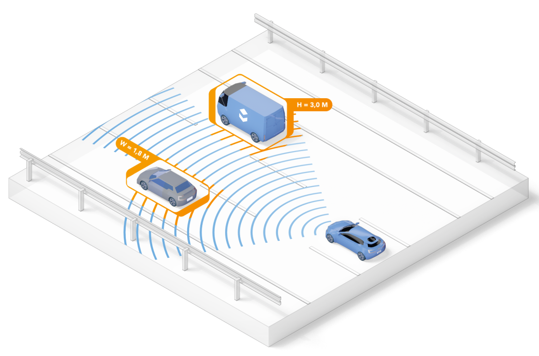
Second, taking the example of a car driving in a tunnel, thanks to improved elevation angle detection performance, imaging radar can now measure the length and width of the entire tunnel and perceive the geometric shapes of objects. When other traffic participants appear in the tunnel, such as trucks, motorcycles, and cars, the imaging radar can provide high-resolution images. In other words, the vehicle’s vision has become more advanced.
Third, if a car is traveling at 80 kilometers per hour on the highway while a motorcycle (a low-reflectivity small object) speeds toward it at 200 kilometers per hour from behind, imaging radar can identify the motorcycle even when they are far apart, and it can recognize that these two objects are moving at two different speeds.
This means that imaging radar not only provides multi-mode functionality but also achieves precise environmental mapping and scene perception by offering ultra-high-resolution images, thereby extending the currently available L2+ level autonomous driving features, such as highway cruise control and lane change assistance. As the level of autonomous driving rises to L3 and above, 4D imaging radar will be able to achieve multiple functions such as mapping, positioning, object contour detection, and object classification. When combined with cameras or pattern recognition and machine learning, the imaging radar system can perceive the surrounding environment at high resolutions of 1° in azimuth and 2° in elevation with ±60°FoV (some say 100°FoV). This enhanced ‘perception capability’ is crucial for achieving fully autonomous driving in complex driving environments.
Overall, as the level of autonomous driving increases, the number of radar sensors installed in each vehicle continues to rise. If a single imaging radar aims to achieve very high angular resolution, it needs to cascade multiple radars at the RF front end to form a larger radar antenna array to achieve imaging capabilities. Therefore, a single forward 4D imaging radar module requires more sensor chips and a more powerful backend processor.
The Imaging Radar Market Gradually Heats Up
NXP has long been a leader in the automotive radar solutions field, and their idea of replacing laser radar with imaging radar has been around for six years.
At CES 2021, NXP introduced an imaging radar solution composed of the S32R45 radar processor and the TEF82xx fully integrated 77GHz RFCMOS automotive radar transceiver, along with scalable angular radar and forward radar solutions based on this. It not only provides high-resolution images, ensuring that all positions of the vehicle are covered by radar, but also enables 360-degree safety surround detection for the vehicle and supports imaging radar target recognition and classification functions, which are crucial for driving in urban environments and automatic parking.
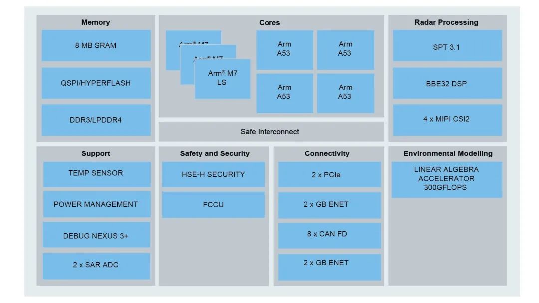
NXP S32R45 radar processor block diagram
The newly launched 16nm radar processor S32R294 features two Power Architecture e200z7 32-bit CPUs with frequencies up to 500MHz for radar signal post-processing and task scheduling, such as super-resolution algorithms, signal clustering, target tracking, etc., along with a dedicated Power Architecture e200z4 core for safety processing, with a maximum lock-step frequency of 250MHz for running function safety-related software, such as AUTOSAR OS, output decision instructions, etc.
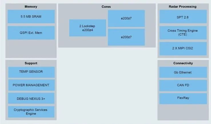
NXP S32R294 radar processor block diagram
The S32R294 integrates a radar processing acceleration unit, referred to as SPT 2.8, which hardware accelerates the most resource-intensive calculations of FFT, magnitude detection, peak detection, histogram statistics, etc., for radar intermediate frequency signals, specifically serving the signal processing of FMCW radar. Its main frequency reaches 430MHz, and the cross-timing engine (CTE) supports precise timing generation and triggering.
Yang Chang, Radar Product Marketing Manager at NXP Semiconductors Greater China, explained that radar intermediate frequency signal processing mainly involves obtaining basic information such as distance, speed, and angle from the intermediate frequency signal, which is calculated by SPT2.8, while post-processing is handled by the Z7 and Z4 cores for super-resolution algorithms, signal clustering, target tracking, decision-making, etc. The obtained target-level data and decision instructions are output to the vehicle control unit or ADAS domain controller via the CAN FD interface.
Compared to the previous device S32R274, the S32R294 has the same size of 7.5mm × 7.5mm but offers additional series scalability, including up to 5.5MB of SRAM; up to 2 MIPI CSI2, suitable for advanced angular radar and forward radar applications using NXP TEF82xx; over 80% software reuse rate; and a power consumption of 0.9W, which is less than half of the previous generation product.
The S32R294 has various configurations that can support full application development from entry-level to high-end, such as one transmit and three receive, three transmit and four receive, six transmit and eight receive, etc., for millimeter-wave radar signal processing.
“The RF part of traditional 77GHz radar usually consists of three chips, responsible for VCO, signal transmission, and reception. However, in NXP’s next-generation 77GHz radar, VCO, signal transmission, reception, and sampling are integrated within a single package, providing the MCU with sampled intermediate frequency signals for signal processing,” Yang Chang believes that millimeter-wave radar will show two major trends in the future: high resolution and high integration.
High resolution can be understood as multiple MMIC chips synchronizing through LO cascading to provide the backend MCU with multiple high signal-to-noise ratio, high sampling rate intermediate frequency signals. The signal processor will need to handle larger data volumes, so the MCU will require more MIPI CSI-2 interfaces, stronger computing power, and dedicated computational acceleration units to process four to eight times more data.
High integration means integrating VCO, signal transmission, reception, sampling, MCU, and other circuits into the same package, applied to short to medium-range radars and parking radars. Compared to multi-MMIC cascading, high integration solutions offer advantages such as miniaturization, low power consumption, and performance that meets demands.
Will it replace laser radar?
Dr. Huang Mingda stated in an interview with this magazine at the beginning of 2021 that from a cost perspective, millimeter-wave radar is definitely cheaper than laser radar; from an industry development perspective, the millimeter-wave radar industry matured about 5-10 years earlier than laser radar, especially compared to solid-state laser radar, so millimeter-wave radar has a significant cost advantage.
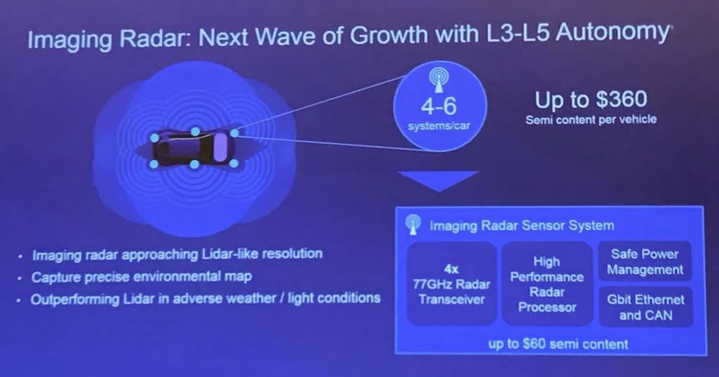
Image source: NXP
According to a report from Lingying Consulting, the cost of cameras and millimeter-wave radar cameras is generally below 600 yuan, with single-lens cameras priced roughly between 150-600 yuan, and surround view cameras priced between 70-500 yuan. In the millimeter-wave radar market, short-range radar is priced around 300-400 yuan, while long-range radar is priced between 800-1200 yuan. The total price of automatic driving vision solutions provided by Mobileye is in the hundreds of dollars.
However, in the field of autonomous driving, due to their respective advantages and disadvantages, millimeter-wave radar, laser radar, and cameras are usually used as redundant and backup systems in L3 and above autonomous driving. For example, laser radar struggles to achieve its claimed performance in rainy, foggy, or dusty weather; cameras are sensitive to lighting conditions; while traditional millimeter-wave radar, despite having the strongest all-weather capability, also has limitations such as low horizontal angular resolution, difficulty detecting crossing targets and stationary targets, etc. Therefore, comprehensively speaking, “the future technology development is not as simple as choosing one of several directions.”
Overcoming Interference Between Automotive Radars
Radar interference is a recognized challenge, but currently, the occurrence probability is relatively low according to market share, so there is not yet a strong awareness of this issue. However, as more cars are equipped with radar sensors, the probability of interference will inevitably increase. Relevant literature reports that when the radar installation rate reaches 50% or more among all vehicles, the probability of radar interference will reach 90% or even higher, which is an urgent issue that all vehicle-mounted radars need to address in the future.
NXP recently published a white paper titled ‘Introduction to Radar Interference in Automotive Applications’, which pointed out that using the same radar frequency spectrum (76-81GHz) and radar waveform parameter configuration, unlike communication systems that have clear channel access rules, is an important reason for mutual interference between automotive radars.
“Different Tier 1 suppliers use different radar parameter configurations, which is completely different from communication systems that have unified rules and are regulated,” Dr. Huang cited an example where two cars approaching each other, both equipped with forward radars, can interfere with each other if their radar signals are transmitted at the same time and frequency or overlap while within each other’s radar field of view (FOV).
The specific impacts can be divided into two situations: First, the background noise can be greatly increased. Simply put, if a radar detects a measured object, a peak will appear on the distance FFT, with the peak value flanked by background noise. When the peak is much higher than the background noise, the radar system can clearly determine that this is an obstacle. However, if it is interfered with, the background noise will rise, causing the true detection signal to be drowned out, leading to misjudgment and serious consequences. Second, the interference signal is in a completely correlated state with the actual transmission and reception signals, resulting in false signals.
The white paper ‘Introduction to Radar Interference in Automotive Applications’ introduces three methods proposed by NXP to combat interference:
Avoid Front-End Saturation
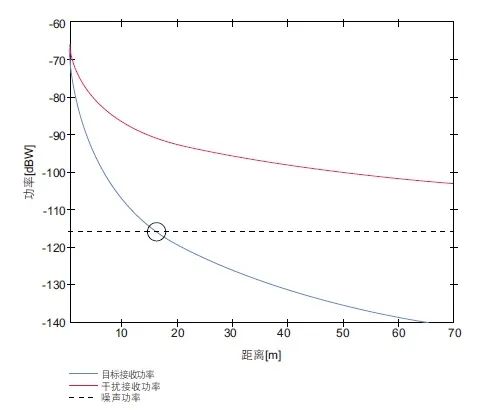
In the diagram below, the blue line represents the effective reflection signal, while the red line represents the interference signal. The effective reflection signal, when returning from the measured object, is attenuated in proportion to the fourth power of the distance; the interference signal, directly emitted from the other radar, is attenuated in proportion to the square of the distance. It can be seen that as the distance increases, the interference signal and effective signal will form a large difference when reaching the receiver, which can easily lead to saturation, so gain adjustments need to be made at the receiving end to prevent saturation.
Processing Digital Interference
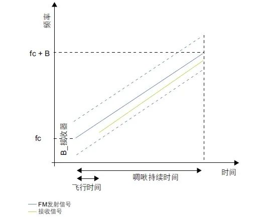
Theoretically, the RF front-end signal is transmitted to the MCU as an intermediate frequency signal, forming a good sine wave shape. If it encounters interference, the amplitude and frequency of the sine wave will typically increase during the interference period. At this time, high-pass filters, threshold detection, or even short-time Fourier transforms can be used to detect interference signals, thereby removing them, and then restoring them to effective sine waves using interpolation methods.
Avoiding Interference
This method is also implemented in the MCU and is more proactive, allowing the transmitted signal to be multiplied by a pseudo-noise (PN) sequence, dynamically adjusting the transmission frequency of the radar waveform, or dynamically adjusting the transmission timing of the radar waveform, etc.
Dr. Huang stated that these three methods are sufficient to address vehicle radar interference in the coming years. However, as the installation rate of radar increases, all OEMs, Tier 1 suppliers, and chip manufacturers will need to jointly establish standardized rules to better address interference. “On this basis, we can even take it a step further, not viewing each radar sensor as an independent unit, but rather as multiple units within the same sensing system. In this system, radar sensors work collaboratively, share information, and achieve the same goal as a larger ecosystem,” he said.
