Follow us for free subscriptions to the latest avionics news.

Abstract
To validate the health management functions of Integrated Modular Avionics (IMA) systems, a technical solution for fault injection through Avionics Full-Duplex Switched Ethernet (AFDX) is presented. Under this solution, a configuration management method for fault data is proposed, along with a sending strategy to address the mismatch between the host data update interval, sending interval, and the AFDX end system timer cycle. A corresponding fault injection device was built, and fault injection software was developed. Experimental tests demonstrated the effectiveness of the aforementioned methods and strategies.
Keywords
Integrated Modular Avionics; AFDX; Fault Injection Technology; Timer; Data Rate


0 Introduction
Avionics Full-Duplex Switched Ethernet (AFDX) is the backbone network interconnection technology in the Integrated Modular Avionics architecture, which has been applied in the avionics systems of Airbus A380 and Boeing B787, equipped with health management and fault prediction (PHM) mechanisms. Typical health management functions compatible with time-partitioned operating systems include PHM processes residing in partitions and PHM partitions residing in modules.
Existing fault injection methods mainly focus on faults in AFDX network communication itself, such as physical layer, link layer, and virtual link (VL) port faults; or through processor hardware for contact or non-contact hardware injection; however, the fault injection methods required for debugging PHM itself without disrupting the operational conditions of the IMA processor are limited to black-box and white-box testing.
However, the correctness and reliability of PHM itself also need to be verified, especially during the design phase of avionics systems. To verify the correctness and effectiveness of the PHM function itself, fault injection must be performed without disrupting the operational conditions of the IMA processor. A software programming-controlled method that artificially inputs or triggers errors in the IMA processor through an integrated network is a fault injection technology solution that meets the above requirements. After analysis, this software-based fault injection based on AFDX can be categorized into various methods such as illegal data input, special signaling input, buffer overflow triggering, and data structure overflow triggering.
The fault injection methods discussed in this paper mainly target illegal data input and special signaling input. The former constructs abnormal flight data that is clearly contrary to physical laws or performance limits based on certain fault scenarios, which can include transmission data from the sampling port and queue port of the AFDX network; the latter targets faults that cannot be directly simulated by software, used in conjunction with debugging processes or program segments residing in the IMA, by sending special signaling to artificially set fault log records, directly triggering the health management function of the partition to observe the response of the PHM process.
First, a fault injection data configuration and management scheme is presented, followed by a proposed and validated timing sending strategy that aligns software timing in a PC host environment with the hardware timing of the AFDX end system card, improving the accuracy of data refresh rates. Finally, actual operational results are reported, demonstrating the effectiveness of this sending strategy in approximating ideal sending moments.
1 Composition of the Fault Injection System
The fault injection system based on the AFDX integrated network mainly consists of three parts: the fault injection function host, AFDX switch, and embedded system, as shown in Figure 1.
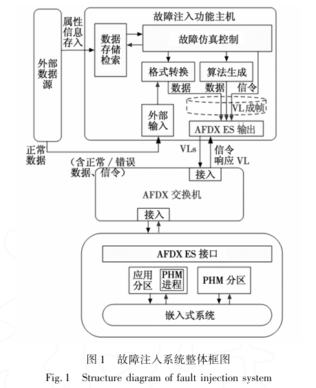
To reduce costs and facilitate programming development, the fault injection function host uses a PC, and the fault injection software is developed using the Visual C++ MFC framework to call the AFDX end system card API. The required normal communication data and injected fault data are defined and set according to the Interface Control Document (ICD) and data file offline format. The host controls the time interval for writing data to the AFDX end system board using a timer. Since the programming environment is a non-real-time operating system, it cannot fully rely on the host’s timing function. It is necessary to load the offline-defined data (including normal data and erroneous data) into the sampling or queue port of the AFDX end system card in a timely and reasonable manner, ensuring that the loaded data meets the timing parameters such as Bandwidth Allocation Gap (BAG) through the co-processing and hardware timing of the AFDX end system card, and is sent to specific modules in specific partitions of the embedded system to drive application programs.
2 Configuration and Management of Fault Data
In general, the injected fault data simulates sporadic errors within a continuous stream of normal data, so the fault injection system must continuously send normal avionics parameters that drive the application programs in the embedded system and insert preset faults according to the simulation scenarios. To manage and configure normal data and fault settings with different data structures, a lightweight database combined with binary data files is adopted, where the former manages the definitions of the interface control files and the structure definitions of the data frames, while the latter stores the offline-generated injected data.
2.1 Data Encapsulation Format
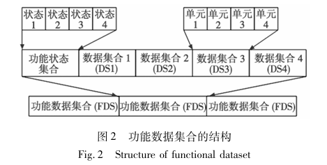
The configuration of fault data encapsulates the data according to the method of functional data set in the AFDX network protocol (see Figure 2), serving as the payload of the AFDX frame. Functional Data Set (FDS) is a method of aggregating data primitives in a message into groups. To enable more efficient storage and retrieval of data by computers, the data configuration must adhere to data alignment principles.
During the design process of the avionics system, the settings of the FDS fields are specified by the Interface Control Document (ICD). The fault injection software needs to define the data structure according to the records of the ICD and manage and maintain the ICD records using a database. Considering that this software is data-oriented, it does not require a fully functional database server but uses a lightweight SQLite relational table for management.
2.2 Data Interface Control and Management
The original data for fault injection includes parameter information or text information, such as local flight parameter information, neighboring aircraft flight information, and digital communication messages. These data are split into individual data units, and the attribute information of each data unit is stored in the SQLite database, as shown in Figure 3.
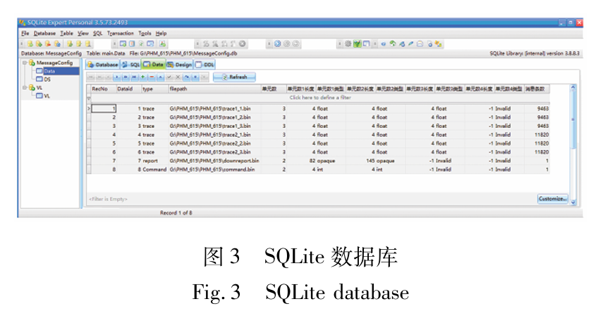
Each data unit corresponds to many data instances; for example, a simulator can generate local position data with a certain trend over a period of time. To meet the demand for random access to these data instances, the original data instances (some simulators output in text form) are uniformly converted to binary files for storage. The binary data has been adjusted to a coherent big-endian format according to AFDX network regulations, directly corresponding to the data bit order of the AFDX frame payload, reducing the overhead of format conversion during transmission.
For instance, for the aircraft’s position and heading information, the FDS format can be used to arrange each data element. First, the local flight information is split into nine units: longitude, latitude, altitude, eastward speed, northward speed, upward speed, pitch angle, roll angle, and heading angle, each assigned a unique ID. Then, the ID, data format, and unit size of each original data unit are stored in the database. Four data units are reserved for each data set (DS) (see Figure 2), allowing users to freely combine data in each DS by filling in the data unit IDs. During transmission, the data unit IDs in the DS are queried in the database to find the corresponding data unit paths to complete the filling of the FDS.
2.3 Fault Data Settings
The fault injection system software includes a data display interface, data configuration interface, and fault injection operation interface. The formats and parameter meanings of normal and to-be-injected data are defined by tables in the SQLite database, with data content sourced from binary files, displayed in list form in the data display interface.
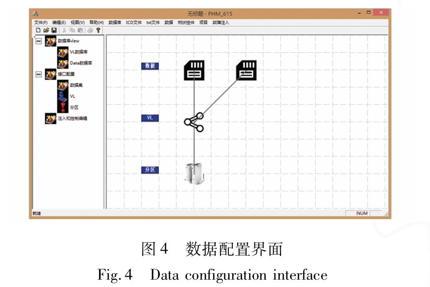
In the data configuration interface, users set the hierarchy of data flow integration and distribution by editing data content and the connections between VL and partition icons, i.e., the data content is encapsulated in the various FDS of the VL data payload, with multiple VLs connecting to specific partitions at the destination node (see Figure 4). Through the pop-up menus of each icon and the navigation on the left, detailed parameters of data content, VL, and partitions can be displayed and edited. After configuration, the sending duration and sending rate for each VL are set, and the interface transitions to the fault injection operation interface.
The fault injection operation interface visually displays the VL data flows of different application data and special instructions in a strip format, indicating the sending with a cursor. The data configuration has already loaded pre-stored normal data into each strip, allowing users to double-click the corresponding strip to set various forms of faults such as value errors or omissions at specified time points in the normal data. Additionally, strips are reserved for placing special instructions corresponding to each tested partition and the entire tested system, allowing signaling-type faults to be injected in the form of fault codes.
3 Software Timing for Fault Injection
To compensate for the insufficient timing accuracy of non-real-time operating systems and to make the sending moments approximate the ideal data update moments, a sending strategy is proposed to address the mismatch between the host application data update rate and the AFDX end system timer cycle, performing software timing for fault injection data frame sending operations.
3.1 Selection of Host-side Timer
After data assembly is completed, the fault injection platform needs to write data to the AFDX end system board at regular intervals. The selectable timers in the Visual C++ development environment include the SetTimer function and multimedia timer.
The SetTimer function is a simple extension of the timer under the ROMBIOS architecture, with a maximum resolution of about 55ms, and its corresponding WM_TIMER message transmission priority is low, resulting in untimely processing.
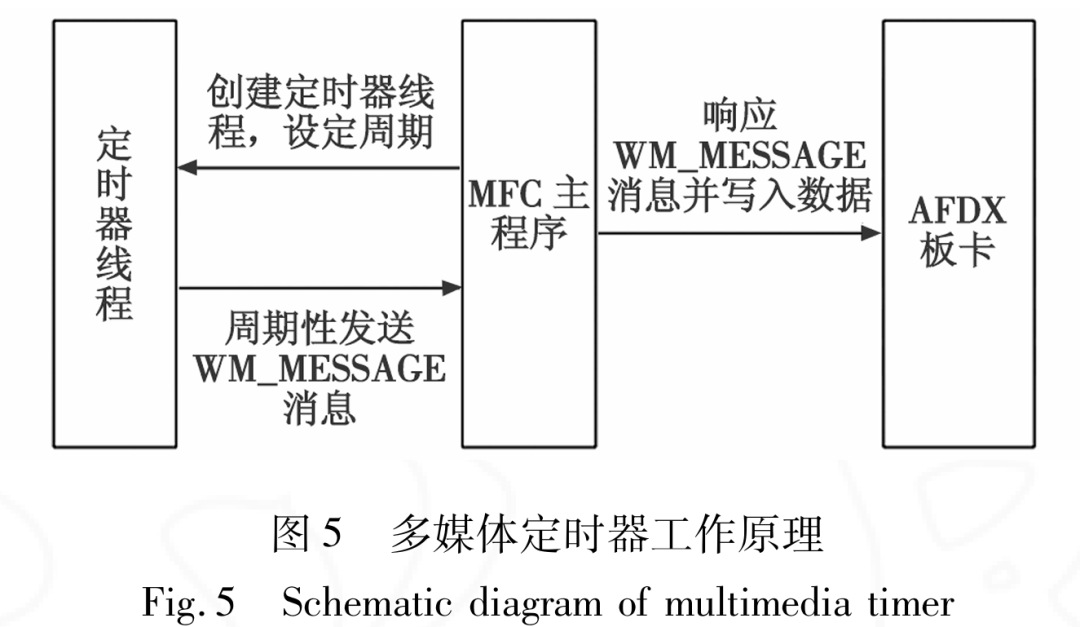
The multimedia timer is created by the TimeSetEvent function in a separate thread, independent of the message transmission mechanism. After an interrupt, the operating system calls a pre-set callback function, which can issue messages to trigger the MFC application to perform sending operations in the callback function, as illustrated in Figure 5. The nominal precision of the multimedia timer can reach 1ms; however, due to the uncertainty of the non-real-time operating system, the interrupt time interval is affected by the current host load, leading to millisecond-level delay jitter.
If the timer cycle is set too small, the thread frequently occupies CPU time slices, which not only leads to low work efficiency and affects the operation of other threads but also deteriorates the timing accuracy due to delay jitter. Conversely, if set too large, it cannot match well with the AFDX data update interval. After design compromise, the interrupt cycle of the multimedia timer is set to 10ms.
To reduce the processing burden on the host, various VLs share a single multimedia timer, which means that the content and quantity of data written during each timer interrupt need to be determined based on multiple user-defined data update intervals and sending intervals. When the data update rate does not match the timer cycle (i.e., not in an integer multiple relationship), the rounding operation of the timing count will cause a certain deviation between the actual sending time and the preset time, necessitating a sending strategy to avoid or minimize this deviation as much as possible.
3.2 Timed Sending Strategy
The VLs of the AFDX network are configured as sampling or queue ports, and traffic shaping is performed at the sending port, meaning that the time interval between the starting bits of adjacent frames in the same VL does not exceed the VL’s BAG.
For VL traffic with sending intervals and BAG less than or close to 10ms (according to ARINC664P7 regulations, these are 1ms, 2ms, 4ms, 8ms, or 16ms), relying solely on software timer interrupts will produce significant errors. The solution is that after each software timer interrupt, a batch of data can be loaded into the sending queue, subject to the BAG constraints of the lower-level AFDX end system card hardware, thereby ensuring their sending repetition frequency. It is worth noting that this solution utilizes the multi-buffering mechanism of queue mode sending; even for VLs transmitting sampled data, they are configured for queue mode sending. Once the data frames enter the switch, there is no distinction between queue or sampling mode, and the destination can still be set to receive normally at the sampling port.
The timed sending operation must also properly handle the data update interval (or so-called “data update rate”) issue. The data update interval is determined by the application and is generally greater than the sending interval and BAG. During the timer interrupt, the corresponding data loading strategy is implemented through programming, writing a batch of messages into the FIFO buffer of the AFDX end system card.
The design of the timed sending strategy ensures that the timing of the timer interrupts precedes the data refresh moments. Thus, for the originally sampling-mode data flow, the first half of this batch of messages contains several repeated messages with current data, followed by the first message after the data update. To approximate the ideal data update and transmission intervals, the following model analysis is required.
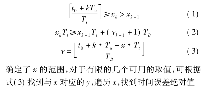
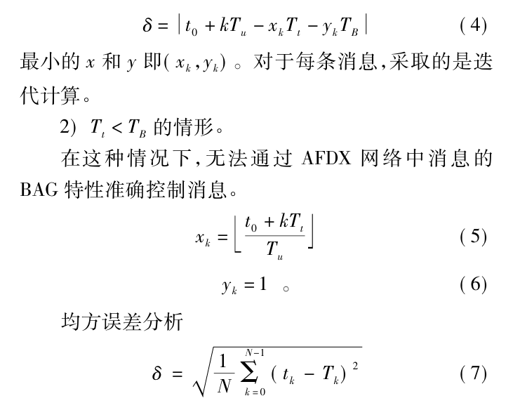
Let the parameters during data transmission be the start time t0, preset sending interval Tu, timer cycle Tt, VL’s BAG TB, and the total number of messages sent N. For a given VL, let the sequence number of the first message after a data update be k, corresponding to the number of software timer interrupts as xk; correspondingly, let yk represent the number of messages that have not been updated before this message.
The timing of batch message loading and the number of messages in the first half of the cache are key to the design of the sending strategy. Thus, the sending strategy is defined as (xk, yk); the initial sending strategy is (t0/Tt, 1), and during operation, (xk, yk) is iteratively calculated based on the previous sending strategy (xk-1, yk-1); the following algorithm is used to obtain the xk value closest to the ideal sending moment.
4 Unit Testing Experiments and Result Analysis
The experimental system consists of a computer, AFDX end system board, and AFDX switch, as shown in Figure 6. The AFDX end system board contains two channels. At the sending end, the fault injection platform written under MFC is used to configure messages (network configuration, VL configuration, and port configuration, etc.), while at the receiving end, the Copilot software from Ballard Canada is used to monitor message frames.
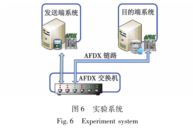
In the above experimental system, fault injection software is used to inject faults into the destination system, and error frame information is monitored at the destination using Copilot software.
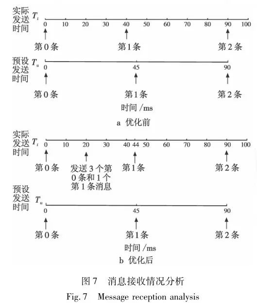
As shown in Figure 7, when sending the second message, the optimized actual sending time is closer to the preset sending time, reducing the time error to some extent.
4.2 Experimental Results and Comparative Analysis
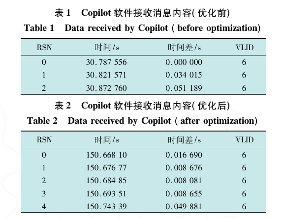
The destination system uses Copilot software to collect and record the received messages. For a given VLID, the loop SN identifiers, absolute sending times, and time differences between adjacent messages are monitored.
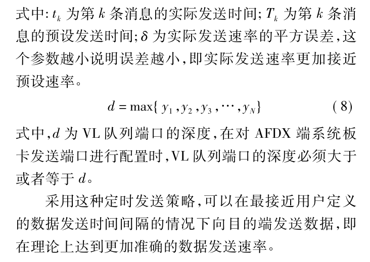
During actual sending, even the multimedia timer will produce errors. Table 1 shows the information of the first three messages received before optimization, with effective message sequence numbers of 0, 1, and 2, respectively. Table 2 shows the corresponding information after optimization. Due to the optimization, the fault injection software sends two repeated messages when sending the second message, resulting in effective message sequence numbers of 0, 3, and 4. The sending times of the three messages before optimization are 0.000ms, 34.015ms, and 85.204ms, while after optimization, they are 0.000ms, 42.097ms, and 91.980ms, with preset sending times of 0.000ms, 45.000ms, and 90.000ms, respectively. δ1=6.920ms, δ2=2.029ms, and the data comparison indicates that this sending strategy has significantly improved the timing accuracy of data sending intervals.
It can be seen that, considering cost control, the use of a non-real-time operating system and PC host, this sending strategy fully utilizes the time determinism instability of the multimedia timer and the high-precision hardware timing of the AFDX end system card co-processor, optimizing the timing of application layer data writing, and reducing the dependency of message sending intervals on the PC host timer. In civil aircraft avionics systems, if the frame interval of data flow is not less than 10ms and can match the magnitude of the corresponding PHM partition call response time, the timing accuracy of the fault injection system described in this paper is usable.

5 Conclusion
The fault injection scheme presented in this paper includes fault data configuration and fault data sending functions, using a PC host and API programming to perform fault injection on embedded platforms, which can address the mismatch between the host application data update rate and the AFDX end system timer cycle to some extent, suitable for experimental validation of the health management functions of the IMA system on embedded platforms. The corresponding software interface and data management methods allow users to design different fault scenarios based on the fault modes of the IMA system for semi-physical simulation of fault injection.
(This article is selected from “Research and Exploration: Process Flow and Applications” by Xu Hai, affiliated with the State-owned Wuhu Machinery Factory and the China Aviation Radio Electronics Research Institute. This article is reproduced solely for the purpose of knowledge dissemination. If there are any copyright issues, please contact us promptly!)