Click the blue text above to follow us
The power test stand is crucial for testing the thrust, torque, RPM, and efficiency of power systems. Integrating sensors into your tests adds another layer of optimization, elevating your performance to a new level.
In the UAV industry, there is ample evidence that collecting data from external sensors can be challenging. To address these issues, we have developed a new software feature called “Input Transformations.” This feature allows you to connect external analog sensors to all our Flight Stand products (drone power test stands, fuel engine test stands), enabling seamless integration of sensor data with power readings.
In this article, we will demonstrate how to connect analog sensors to your test stand, provide use cases highlighting the advantages of additional sensors, and discuss some challenges you may face during testing.
01How to Connect External Sensors to Your Test Stand?
In this section, we will introduce how to connect external sensors to your test stand. We will demonstrate how to use a sound sensor to showcase how to optimize for a quieter flying experience using propeller noise measurements.
Specifically, we will measure the decibel levels produced by the power system (Xoar 26-inch propeller + AXI 8110 motor) by connecting the SEN0232 sound level meter to our Flight Stand 15 Pro test stand. This probe operates at a 5V voltage input and can measure sound levels from 30dBA to 130dBA.
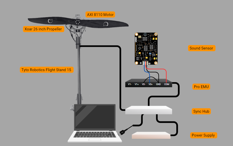
Figure 1: Test Stand Setup
You can test various sensor positions and motor/propeller combinations to determine which configuration minimizes noise.
Steps to Connect the Sensor:
In the Flight Stand software:
1) Verify that the Flight Stand hardware is connected via USB;
2) Navigate to the Input Transformations tab;
3) Click “Add new transformation”;
4) Under “Name,” you can type an alias for the sensor (e.g., “Sound Sensor”);
5) Select your unit type or choose “Custom Unit” and enter “dB” for decibels;
6) Assign the voltage general analog input to variable “a”;
7) In the “Formula” field, type the conversion formula provided in the sensor data sheet, in this case: a * 50 : Decibel value (dBA) = Output voltage (V) × 50;
8) Enter system limits based on the data sheet specifications to trigger an automatic motor cutoff when the sound level exceeds the defined range;
9) Click “Save”;
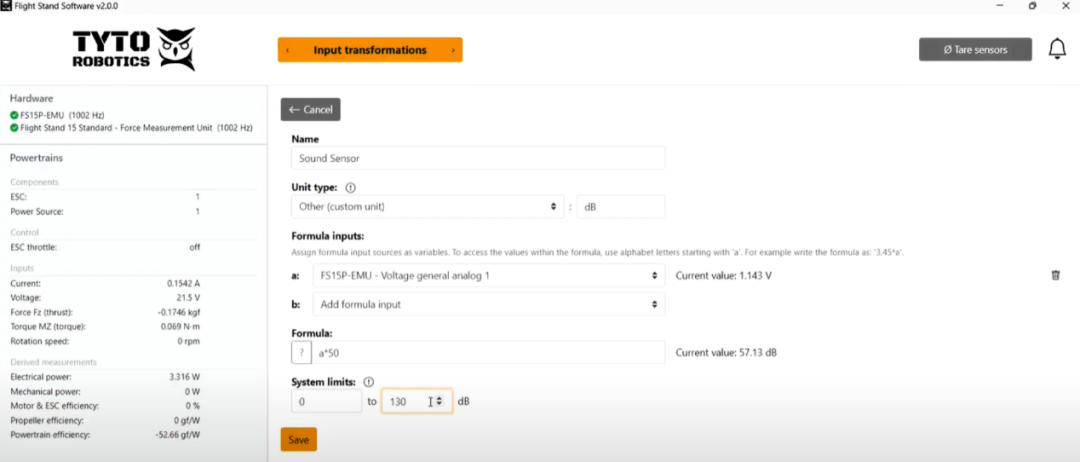
Figure 2: Flight Stand Software Setup
10) Navigate to the Powertrain Mappings tab;
11) Click “Extra mappings,” then select “Transformations-Sound Sensor.” You can now see real-time data from the sensor in the left panel and live graph;
12) Continue as you would with regular testing. When you download the CSV file, the sound sensor data will be exported along with the other results.
After analysis, the graphical results below indicate that the power system produces 76.18dB of noise at a maximum throttle of 1500μs and 1099.45RPM. We will then decide if this is an acceptable noise level; if not, we can continue testing other powertrain combinations for lower noise levels.
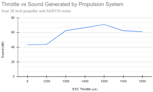
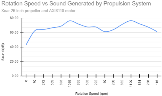
Figure 3: Propeller Noise Experiment Results
This example of connecting an analog sensor to the test stand highlights the potential of external sensors in significantly enhancing power system development.
02Why Use External Sensors to Test Power Systems?
Sensor data is key to making informed decisions related to UAV development. The additional data provided by sensors can lead to the creation of more efficient, reliable, and safer drones.
Here are several reasons to add external sensors in a testing setup:
Collect Additional Performance Data
Efficiency is one of the most important metrics for evaluating drone performance. Here are some off-the-shelf sensors that can help you achieve higher efficiency:
-
Cylinder Pressure Sensor: Monitoring cylinder pressure variations allows you to fine-tune the fuel-air mixture, thereby improving the performance of power systems using internal combustion engines.

Figure 4: Qishi Le 6125C Piezoelectric Pressure Sensor
-
Thermal Sensors: Tracking the temperature of critical components to prevent overheating, reducing the risk of heat-related environmental hazards, and ensuring that the power system does not adversely affect its surroundings. Note that the Tyto Robotics temperature sensor directly plugs into the force measurement unit.
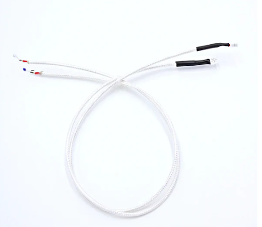
Figure 5: Tyto Robotics PT-100 Temperature Sensor
Improve Reliability
Testing performance with external sensors based on environmental factors helps predict discrepancies in how the drone will operate under real conditions. Examples of such sensors include:
-
Humidity Sensors: Testing with various humidity levels can help you determine how to maintain consistent thrust output under different environmental conditions.
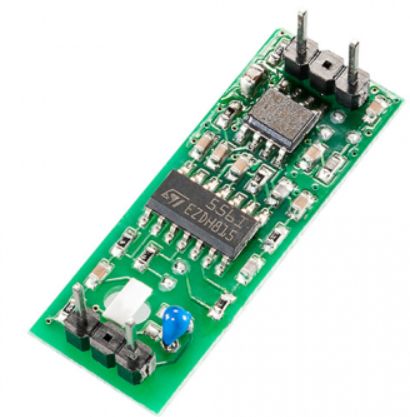
Figure 6: B+H YTE-ANA-1735 Calibration Humidity Module
-
Wind Speed Sensors: Measuring airflow around the power system can help you identify areas of laminar and turbulent flow, allowing you to adjust designs to reduce drag and improve maneuverability.
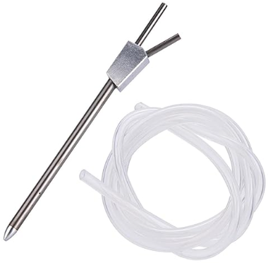
Figure 7: Jadeshay Pitot Tube for Flight Control
Measure Noise
You can also use external sensors to reduce operational risks, especially in specialized UAV flight applications such as agriculture, military, and logistics. For example:
-
Sound Sensors: Monitoring noise levels to detect excessive noise pollution and potential mechanical issues, helping ensure that the power system operates within environmentally acceptable noise ranges.

Figure 8: DFRobot SEN0232 Sound Level Meter
Challenges of Testing with External Sensors
Testing power systems with external sensors presents several challenges that must be addressed to ensure accurate and reliable data collection.
-
Interference and Noise: Power systems generate electromagnetic interference (EMI) and mechanical vibrations that can affect the accuracy of external sensors. It is essential to consider using stabilization techniques to minimize these effects and ensure reliable sensor readings.
-
Data Integration: Integrating data from multiple sensors can be complex. Ensuring correct interpretation of data collection requires advanced software algorithms and data processing capabilities.
-
Durability: External sensors used in power testing must withstand harsh working conditions, including high temperatures, vibrations, and potential impacts.
03How Our Flight Stand Addresses These Issues?
-
All-Solid-State Deformation Measurement System: Minimizes the impact of power system vibrations on data measurement.
-
Seamless Data Integration: The Flight Stand software synchronizes data measurements with a sampling rate of up to 1,000Hz, enabling seamless data integration.
-
Custom Formulas: The software supports custom formulas to match any algorithm being tested, allowing you to use any sensor that meets your operational requirements.
UAV / eVTOL Power Testing Solutions
END Scan to Follow UsContact UsPhone: 010-88570498
Email: [email protected]