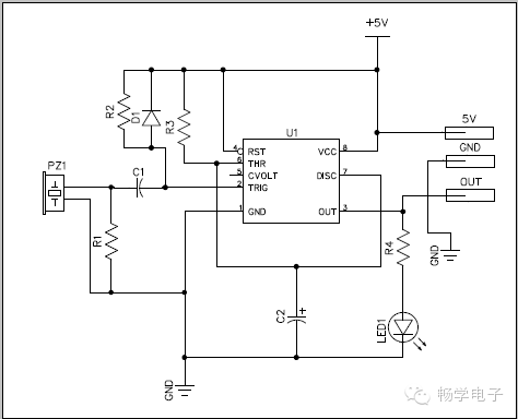
The piezoelectric trigger switch circuit described here is a microcontroller-compatible impact sensor switch module operating on a 5V DC power supply. The entire circuit can be assembled on a standard 5×7 cm circuit board. The piezoelectric ceramic element (Pz1) can also be easily mounted on the PCB. This module provides a “logic” (H) output when the sensor (Pz1) detects a valid impact. By default, this high signal lasts for nearly 1 second. However, you can modify the RC time by adjusting the values in the CMOS monostable circuit built around the m7555cn constant part (U1).
A 5mm LED (LED1) is added as an effective visual indication of the output state. Imagine the fun you can have creating a drum that shakes the house. This circuit allows you to connect your Arduino to the drum. Disco lights flashing in sync with the bass drum beat is another example of an application!
Schematic diagram of the impact sensor switch circuit

7555 Datasheet
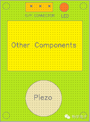
Proposed circuit board layout wiring diagram. First, apply a thin layer of glue to the marked area on the PCB where the plastic washers (with appropriate diameter) will be placed, and set aside until the glue hardens. Next, apply glue dots on the washer to attach the piezoelectric sensor (with pre-soldered wires) and solder the wires to the circuit board. Decide where you want to route your wires before completing this step, as it will be difficult to adjust them afterward. Now you can finish the assembly by soldering the remaining components as indicated in the schematic diagram. After construction, gently tap or press the piezoelectric sensor with your fingertip or a small hammer to test the circuit. Each time the piezoelectric element is activated, the red LED will light up for about one second. Please note that the piezoelectric element is fragile, so handle it gently.
Parts List
1: m7555cn (NXP)
D1: 1N4148
LED1: 5mm Red
P: 27mm Piezoelectric Ceramic Element (Piezo Disk)
R1: 470k ¼W
R2: 100K ¼W
R3: 100K ¼W
R4: 1.5K ¼W
C1: 1kpf (102) Ceramic
C2: 10uF Tantalum / 16V
(Plastic Washer: 25mm outer diameter × 20mm inner diameter × 2mm thick)
Notes
The detection sensitivity of this circuit is intentionally reduced to a large extent. Environmental vibrations will not trigger the circuit.
m7555cn is the CMOS version of the IC555. The decoupling capacitor at pin 5 of the IC is not very necessary for this version.
If you are an experienced hobbyist, try building the circuit using surface mount components. This will reduce the size of the module and enhance the stability of the circuit. U1 in SO-8 package part number is m7555cd (prototype and package testing).
Since the piezoelectric sensor can output a high voltage signal, it is good practice to include a Zener diode to protect the input.
Do not expect precise results from this circuit. If your application requires simple remote sensing, this could be a great choice and save money!