
In the practical application of wireless communication modules, onboard antennas are often used due to size constraints. If the antenna is not properly handled, it can significantly affect communication performance. This article will explain in detail how to optimize the details to achieve the best performance of wireless modules.
The transmission distance of wireless modules depends greatly on the antenna used, in addition to the module’s own performance. Common antennas include PCB antennas, spring antennas, ceramic antennas, rod antennas, and suction cup antennas. Different antennas have varying performance, but the same antenna used differently can have communication distances that differ by several times or even dozens of times. The later discussion will focus on the VSWR and radiation gain affecting PCB antenna performance.
1.1 Antenna Basics
The basic definition of an antenna: A uniform section along the transmission line, where the distance between the two lines is much smaller than the wavelength, allows energy to propagate as plane electromagnetic waves with minimal loss (very little radiation); along the gradually expanding section of the transmission line, where the distance between the two lines reaches or exceeds the wavelength scale, the wave will radiate into free space, demonstrating the properties of an antenna.
In simpler terms: as shown in Figure 1.1, the two lines of the transmission line have opened up, and these two lines are the antenna; when the two lines are close together, their electromagnetic fields cancel each other out and become a transmission line as shown in Figure 1.2. This article discusses how to transmit power more efficiently along the transmission line.
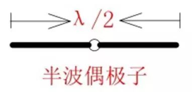
Figure 1.1 Half-wave Dipole

Figure 1.2 Transmission Line
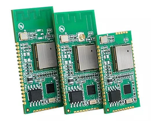
2.1 Modules with PCB Antennas
Generally, when the requirement for transmission distance is not high, but the module size requirement is high, PCB antennas are commonly selected in the 2.4GHz frequency band. For applications requiring higher communication distances, rod antennas and suction cup antennas with higher gain and efficiency are needed.
Suppliers typically provide modules with PCB antennas that are optimized based on the module’s ground simulation, as shown in Figures 2.1~2.3, with a maximum radiation gain of 2.75dBi and a VSWR of less than 2 in the 2.4GHz frequency band.

Figure 2.1 Module Inverted F Antenna Simulation
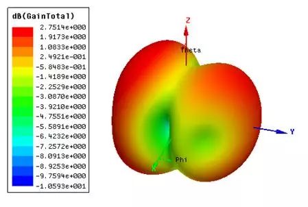
Figure 2.2 Module Inverted F Antenna Radiation Pattern
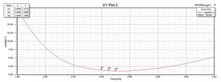
Figure 2.3 Module Inverted F Antenna VSWR
2.2 Ground Plane Below the Antenna
The PCB antenna is only one end of the dipole antenna, with the ground of the board acting as the other end of the antenna. During practical use, it is important to maintain a distance between the board’s ground and the antenna to avoid changes in the antenna’s resonance that could lead to decreased radiation efficiency.
When simulating the ground plane below the antenna as shown in Figures 2.4~2.7, the antenna’s impedance strays far from 50Ω, and the radiation gain is only -3 dBi. The radiation gain has decreased by nearly 6dB from the original, and the VSWR is also significantly greater than 2. Clearly, having a ground plane below the antenna severely impacts its radiation efficiency.
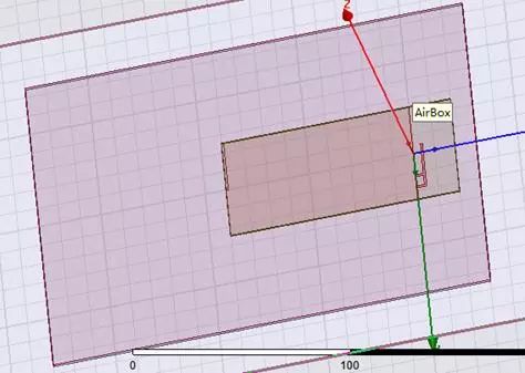
Figure 2.4 Ground Plane Simulation Below Antenna
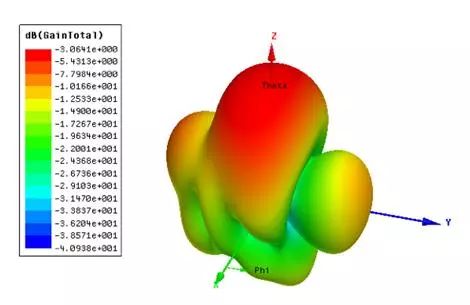
Figure 2.5 Ground Plane Radiation Pattern Below Antenna

Figure 2.6 Ground Plane Smith Chart Below Antenna
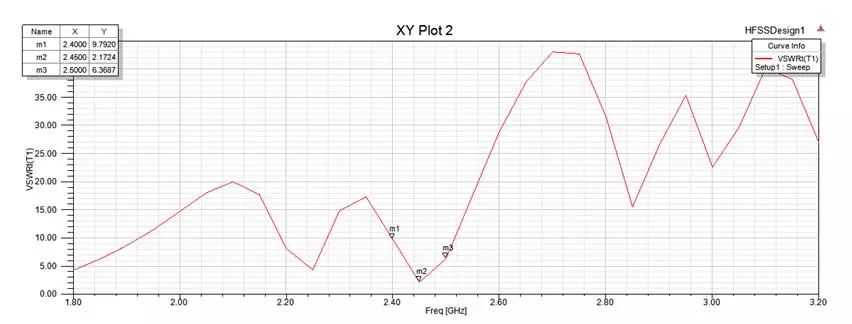
Figure 2.7 Ground Plane VSWR Below Antenna
2.3 Dielectric Below the Antenna
When there is no ground plane below the antenna, but the dielectric is not hollowed out, the thickness of the dielectric increases relative to the antenna. The dielectric constant and thickness of the dielectric affect the wavelength of the transmitted wave, which can lead to frequency shifts and decreased radiation efficiency of the antenna, as shown in Figures 2.8~2.10.
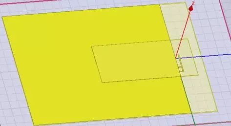
Figure 2.8 Simulation with Dielectric Below Antenna
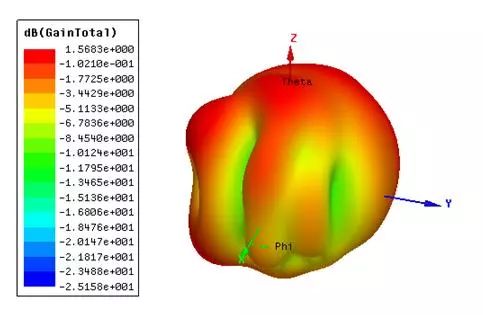
Figure 2.9 Radiation Pattern with Dielectric Below Antenna
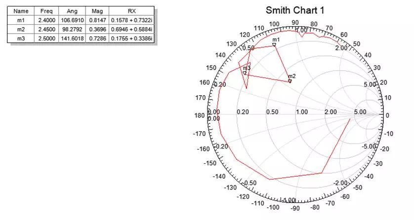
Figure 2.10 VSWR with Dielectric Below Antenna
2.4 Clearance Around the Antenna
When both the ground and dielectric below the antenna are hollowed out, the simulation results are almost identical to the module simulation. As shown in Figures 2.11~2.13, the antenna gain is 2.4dBi, which differs only by 0.35dB from the original, and the VSWR in the 2.4GHz frequency band is also below 2. In practical use, it is only necessary to fine-tune the antenna frequency point through impedance matching, and in cases of wider bandwidth, no re-matching is needed.
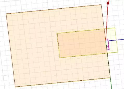
Figure 2.11 Clearance Simulation Around Antenna
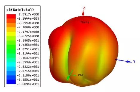
Figure 2.12 Clearance Simulation Around Antenna
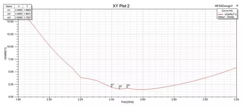
Figure 2.13 VSWR with Clearance Around Antenna
During use, antennas should avoid having other objects nearby to prevent interference with the resonance point of the antenna, which can lead to decreased radiation efficiency. It is especially important to ensure that there is no ground (including batteries) next to the antenna, as this will significantly reduce the antenna’s performance.
Spring antennas are similar to PCB antennas, using the board’s ground as the other end of the antenna. It is also not recommended to have other materials or ground close to the spring antenna. The ideal physical position between the spring antenna and the ground is as shown in Figure 1.1, where one side is ground and the other is the antenna, with the two extending in opposite directions.
The ZLG ZhiYuan Electronics WM6201 series Wi-Fi module is designed for complex industrial environments, with the PCB antenna matching design rigorously tested and validated, optimizing signal quality to enhance signal strength and penetration. Multiple safeguards ensure seamless connectivity for IoT devices, providing a perfect experience with full signal strength! The onboard antenna has a line-of-sight communication distance of 80m, while an external antenna can reach up to 120m.
ZLG ZhiYuan Electronics Introduction
Guangzhou ZhiYuan Electronics Co., Ltd. is a subsidiary of Guangzhou ZhiYuan Electronics Co., Ltd., founded by renowned embedded system expert Professor Zhou Ligong in 2001. It is a national high-tech certified enterprise and the Guangdong Provincial High-end Industrial Control Measurement Instrument Engineering Technology Research and Development Center.
Strategy:Industrial Intelligent IoT Ecosystem
ZLG integrates “chip + AWorks software platform + artificial intelligence” to design high-value-added modules, boards, and high-end measurement instruments from “chip” to “cloud”. Through wired and wireless methods, connect to the ZWS (ZLG Web Service) IoT cloud for big data processing, building an industrial intelligent IoT ecosystem.
Values:Professionalism and Focus Achieve Dreams
Focusing resources and concentrating on the development strategy of the industrial intelligent IoT ecosystem to achieve dreams.
Corporate Culture:Common Struggle, Shared Benefits, Mutual Achievement
Implementing the “Climbing Plan” to establish a growth mechanism for talent;
Implementing the “Partner Entrepreneurship and Benefit Sharing” plan to create a vibrant and positive team.