A few days ago, a frustrating problem left me quite unhappy.The final solution was simple, but the problem itself had me deep in thought.
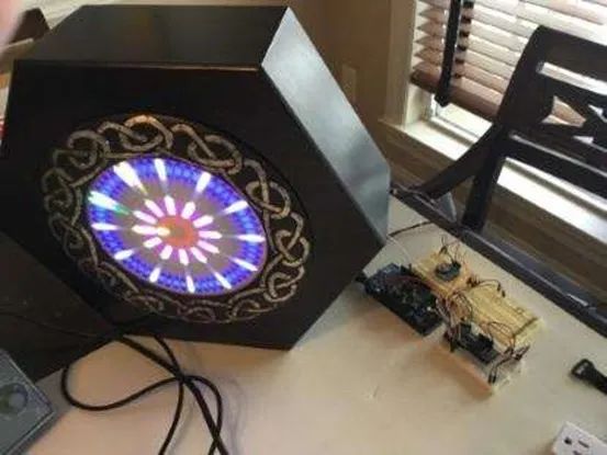
I thought it was time to tidy up the messy breadboard circuit, as all the issues began at that point. (Note: These circuits are mainly used to drive my Cunning Chronograph).
In the end, I stacked the boards neatly and beautifully, as shown in the picture below. At the bottom is an Arduino Mega. On top of it is the same custom audio spectrum analyzer (SA) expansion board made specifically for my BADASS display by my friend Duane Benson.
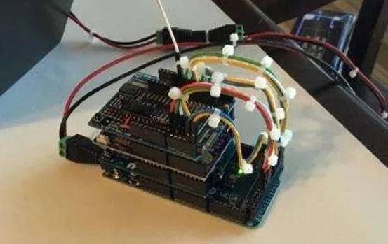
The second layer from the top is a custom sensor expansion board, which currently only has a Real-Time Clock (RTC), but I will soon add a pressure/temperature sensor and a 9DoF (9 degrees of freedom) sensor, which includes a 3-axis accelerometer, a 3-axis gyroscope, and a 3-axis magnetometer.
Finally, prominently at the top is a ready-made Arduino proto-shield prototype expansion board—this is where the annoying problem I mentioned at the beginning of this article occurred, as it is connected to the Simblee breakout board, allowing me to control the Cunning Chronograph via Bluetooth on my iPad.
Now let’s take a look at a simple schematic that shows the 29-GPIO Simblee breakout board installed in the center of the Arduino Uno proto-shield prototype expansion board.
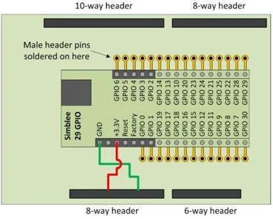
The Simblee breakout board requires a 3.3V power supply. The Arduino Mega runs on 5V, but it does provide a 3.3V voltage rail, as shown in the above image. Only the 3.3V power and ground signals are directly connected to the Simblee pins of this Arduino. When this expansion board is connected to the top of the Arduino Mega, there are also 13 GPIO pins from Simblee (configured as OUTPUT) connected to the same number of Arduino GPIO pins (configured as INPUT_PULLUP). These signal connections use jumper wires instead of the pin headers used in the board stack.
This is the situation I encountered. When I first made the expansion board stack, everything was perfect. However, last weekend, I decided to transplant the power supply and electronic components into the Cunning Chronograph enclosure. I always underestimate how long such things take, as I hoped it would look a bit more professional, so I spent a lot of time cutting the wires to the right lengths and making harnesses and other things.
Finally, I sat down to enjoy the good feeling of completing the work, gently pressed the power switch with my finger, but… nothing happened! My mood instantly dropped to freezing point—what on earth happened? Let me explain it in detail.
To help you better understand what I’m saying, I drew a simple schematic of the situation I encountered.
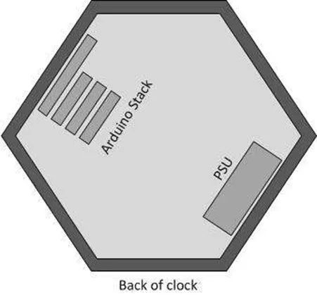
This is the rear view of the Cunning Chronograph. The power supply is installed in the lower right corner inside the enclosure (it cannot be installed at the bottom as it would interfere with the plug board), while the Arduino stack is installed in the upper left corner inside it, aiming to keep it as far away from the power supply as possible (I don’t know if this is necessary, but I wanted to minimize any potential impact the power supply might have on my magnetometer).
Simply put, I took out my incredibly reliable multimeter and started probing around. I quickly discovered that when probing the power and ground pins of the Simblee, there was only 1.5V on the 3.3V power pin of the Simblee breakout board.
“This is interesting,” I thought. Even more interesting was that when I probed the 3.3V and ground pins of the Arduino with my multimeter, it showed the full 3.3V voltage.
Next, I pulled the Simblee expansion board out of the stack and connected the 3.3V and GND pin headers from the top of the stack to the 3.3V and GND pin headers on the Simblee expansion board via jumper wires! Okay, everything was back to normal.
When I happily reconnected the expansion board to the stack and powered them up again, I thought to myself, “Ha! This was just a random glitch, one of those things we can never fully understand.”
But I couldn’t help but think back to the fact that there was only 1.5V on the 3.3V power pin of the Simblee. How could it be that with only the pin headers that form part of the stack between the two ends, there was 3.3V at the bottom of the stack and only 1.5V at the top? Where did the remaining 1.8V go?
I want to say that I finally solved the problem, and everything is back to the way it should be, so now I feel relaxed and happy again. However, I still cannot be 100% certain about the exact cause of the problem, as there are three possibilities, which I only learned after I fixed the issue. The world is full of wonders; perhaps my fix just happened to solve the faults caused by these three reasons! Reader, can you guess what these three reasons are?
Editor: Luffy Liu


👆Long press the image to scan for application👆