
EEWorld
Electronic News Sharp Interpretation
Technical Content Updated Daily

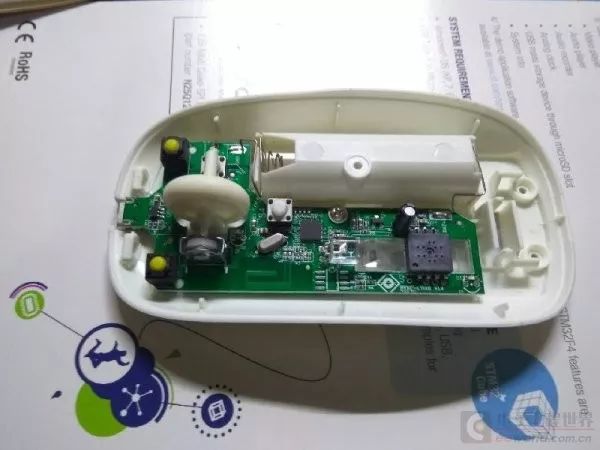
Wireless mice are very convenient, but the battery life is not very good. Even rechargeable batteries need to be charged. Many mice come with a power switch to save battery energy, but it’s easy to forget to turn it off after use, leading to waste. Although most mice have an automatic sleep function, it seems that the sleep effect is not ideal. I have tried several 2.4G wireless and Bluetooth mice, and they often have battery issues. I couldn’t find a suitable one, so I decided to modify one myself. Ideally, I want to use the mouse as soon as I pick it up, and have it automatically switch off after being put down for a while. This way, regardless of whether the mouse’s low-power function is good enough, it won’t drain the battery, making it worry-free to use. I just happened to have a spare Bluetooth mouse, so I got started on the modification.

-
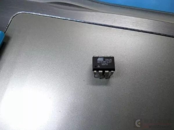
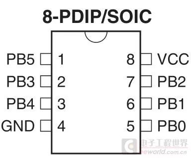
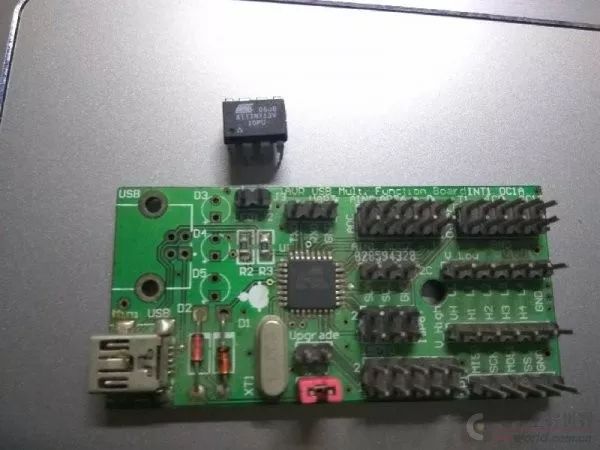
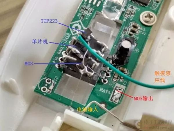
ATTiny13V, an 8-pin AVR microcontroller
-
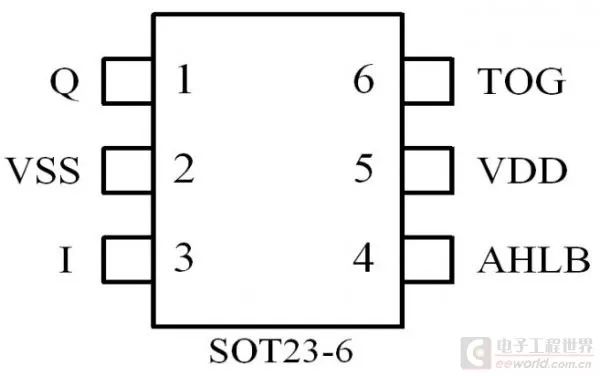
TTP223, a single touch sensor
-
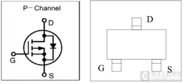
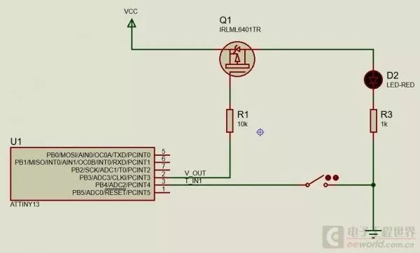
SI2301, P-MOS
#define F_CPU 4800000L
#include <inttypes.h>
#include <avr/io.h>
#include <avr/interrupt.h>
#include <avr/sleep.h>
#include <util/delay.h>
#include “uhd.h”
#define V_OUT B, 3
#define T_IN1 B, 4
void init()
{
IO_dir(V_OUT, IO_OUTPUT);
IO_set(V_OUT);
//IO_pullup(T_IN1, PULLUP_ENABLE);
IO_dir(T_IN1, IO_INPUT);
WDT_sleep(40);
}
uint8_t cnt = 0;
uint8_t mode = 0;
int main()
{
init();
while (1)
{
WDT_sleep(8);
if(IO_in(T_IN1) == 0)
{
IO_clr(V_OUT);
mode = 1;
cnt = 60;
}
else
{
if(mode)
{
cnt–;
if(cnt == 0)
{
mode = 0;
IO_set(V_OUT);
}
}
}
}
return 0;
}
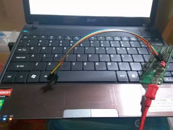
Download the program to the microcontroller first, then solder the signal line, and it’s done. A long wire was used as the touch sensor and fixed to the underside of the top cover.
-
After the first installation and running, I found a problem: the TTP223 output could not pull to 0V, only 2.8V. Upon checking, I found that I had enabled the pull-up resistor for the IO, and after disabling it, it was normal.
-
To better prevent interference, multiple touch signals could be used for control; only when multiple signals are valid at the same time would the power turn on, resulting in better performance.
-
For a mouse powered by a single AA battery, since the voltage range is 0.9-1.5V, the components above cannot be used. Therefore, it is necessary to select suitable components or use a boost method.
For the complete Proteus8 program, please click to read the original text to download.
Recommended Reading
Content | Understanding Five Common Internal Noises
Content | How to Characterize Noise in Operational Amplifier Circuits?
Content | EMC Design Experience in the Early Stages of Electronic Product Design
Content | An In-Depth Analysis of CAN Communication on STM32
Content | DC Motor Drive Circuit and Design Experience Sharing
Content | A Compilation of Circuit Diagrams Every Electronic Engineer Must Master
Content | A Single Article to Help You Understand the Difference Between DC-DC and LDO
Content | FreeRTOS Learning Notes – Software Structure of FreeRTOS
Content | Classic Operational Amplifier Circuit Analysis

The following WeChat public accounts belong to
EEWorld (www.eeworld.com.cn)
Welcome to follow by long pressing the QR code!
EEWorld Subscription Account: Electronic Engineering World

EEWorld Service Account: Electronic Engineering World Welfare Society