Wireless mice are very convenient, but the batteries are not very durable. Even rechargeable batteries need to be charged. Many mice come with a power switch to save battery energy, but it’s easy to forget to turn off the switch after use, leading to waste.
Although most mice have an automatic sleep function, the effect of sleep doesn’t seem ideal. I have tried several 2.4G wireless and Bluetooth mice, and have often been troubled by battery issues without finding a suitable one, so I thought about modifying one myself.
Ideally, the mouse should be usable as soon as you pick it up, and automatically turn off power after being placed down for a while. This way, regardless of whether the mouse’s low power consumption function is good enough, it won’t drain the battery, making it more worry-free to use. I happened to have a spare Bluetooth mouse, so I got to work on modifying it.
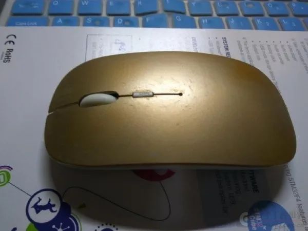
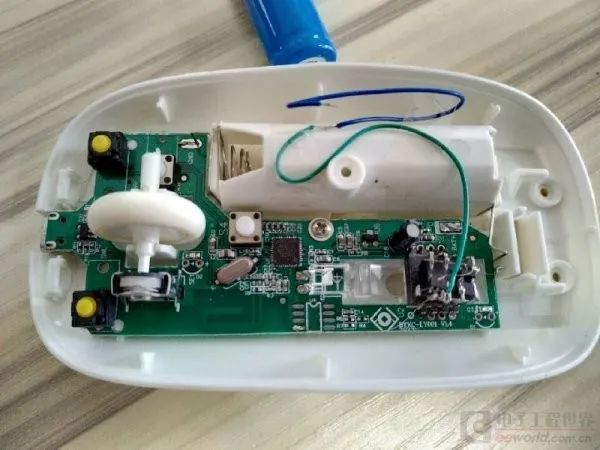
This mouse is the most common public mold mouse. It is powered by a 14550 lithium battery, and possibly due to the small battery capacity and usually not having a power switch, it can typically be used for 7-15 days on a single charge (depending on usage frequency).
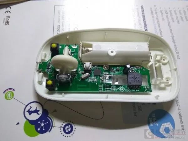
The mouse is easy to disassemble. After removing the battery, you can see the fixed screws. This mouse is secured by only one screw, and there are no screws under the mouse pads (some mice may have screws at the back under the pads). After removing the screw, it is easy to separate the upper and lower parts of the mouse and see the mainboard inside.
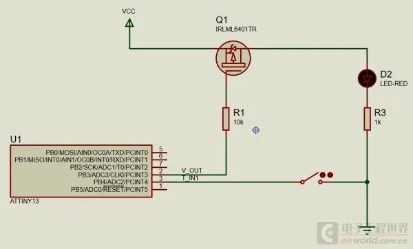
To achieve the earlier idea, it’s actually not difficult. You only need a low-power microcontroller (most microcontrollers nowadays can do this), a touch button chip, and a P-MOS transistor. The touch button chip detects when a hand touches the mouse, and when the mouse is touched, it outputs a signal. Once the microcontroller detects this signal, it controls the MOS transistor to turn on and supply power to the mouse; when the signal disappears (the hand is removed), it cuts off the power after a delay, thus automatically saving battery energy. Some microcontrollers support high current output pins (output current not less than 50mA), in which case the MOS transistor can be omitted.
Having determined the basic plan, the next step is to select the appropriate components. A lithium battery’s voltage range is 2.7-4.2V, so you need to choose a microcontroller that supports 2.7-5V, otherwise, an LDO is needed to prevent the voltage from exceeding the range. The MOS and touch chip also need to be selected according to the appropriate voltage range. These components are relatively easy to find, and I believe everyone has some familiar ones. However, the fun of DIY lies in trying to use as few costs and existing items as possible, rather than spending a lot of money to buy a ready-made one. So I rummaged through my junk box and found the following components, which just meet the requirements:
-
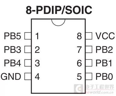
ATTiny13V, an 8-pin AVR microcontroller -
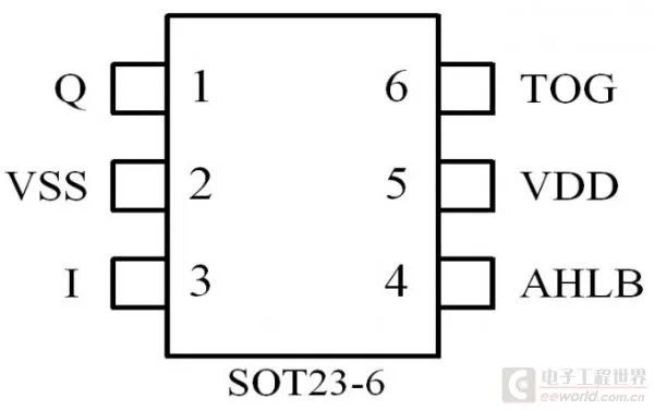
TTP223, a single touch sensor -
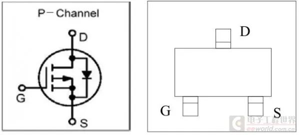
SI2301, P-MOS
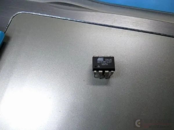
ATTiny13V is an 8-pin microcontroller with a maximum clock frequency of 10M, 1KB flash, 64B RAM, and 64B EEPROM. The power consumption in sleep mode is about 5uA (with the watchdog enabled).
TTP223 is a chip in SOT23-6 package that supports multiple output modes and self-calibration. To keep the program simple, I used the direct output mode here, which is active low. Therefore, TOG needs to be grounded, and AHLB connected to VCC.
SI2301 is just a regular MOS, and other similar models can be used.
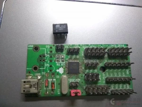
I haven’t used AVR microcontrollers for many years, so I found my programmer, which I DIYed back then, using the AVRUSB method. I also found an old computer with XP installed because systems after Windows 7 cannot directly use AVRUSB.
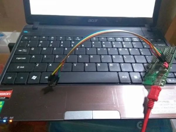
Since I didn’t have (and didn’t need) a simulator, I used Proteus for the program. In Proteus, you can simulate, write code, run simulations, and set breakpoints. If the simulation results are normal, there usually aren’t any big issues.
I hadn’t used AVR for a long time, and I had forgotten some usages. Fortunately, I have a general driver layer I wrote before, and I was able to complete the functionality quickly without looking at the manual. I used one IO for touch detection and another for MOS control. The microcontroller usually sleeps, waking up through WDG timing, and the power consumption in sleep mode should be less than 20uA. I didn’t feel this deeply before, but now I increasingly realize how important a good HAL is.
-
#define F_CPU 4800000L
-
#include <inttypes.h>
-
#include <avr/io.h>
-
#include <avr/interrupt.h>
-
#include <avr/sleep.h>
-
#include <util/delay.h>
-
#include “uhd.h”
-
#define V_OUT B, 3
-
#define T_IN1 B, 4
-
void init()
-
{
-
IO_dir(V_OUT, IO_OUTPUT);
-
IO_set(V_OUT);
-
//IO_pullup(T_IN1, PULLUP_ENABLE);
-
IO_dir(T_IN1, IO_INPUT);
-
WDT_sleep(40);
-
}
-
uint8_t cnt = 0;
-
uint8_t mode = 0;
-
int main()
-
{
-
init();
-
while (1)
-
{
-
WDT_sleep(8);
-
if(IO_in(T_IN1) == 0)
-
{
-
IO_clr(V_OUT);
-
mode = 1;
-
cnt = 60;
-
}
-
else
-
{
-
if(mode)
-
{
-
cnt–;
-
if(cnt == 0)
-
{
-
mode = 0;
-
IO_set(V_OUT);
-
}
-
}
-
}
-
}
-
return 0;
-
}
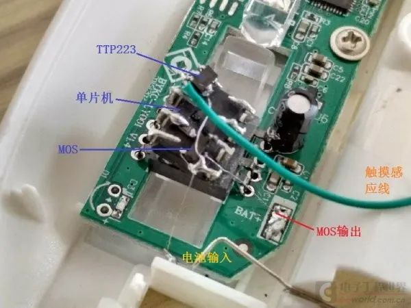
Download the program to the microcontroller, then solder the signal wires, and you’re done. A long wire was used for touch sensing and fixed under the upper cover.
-
After the first installation and running, I found an issue where the TTP223 output could not be pulled to 0V, only to 2.8V. Upon checking, I found that the pull-up resistor for the IO was enabled in the program, and after disabling the pull-up, it worked normally. -
To better prevent interference, multiple touch signals can be used for control. The power should only be turned on when multiple signals are simultaneously valid; this will yield better results. -
For mice powered by a single AA battery, since the voltage range is 0.9-1.5V, the above components cannot be used. Therefore, appropriate components need to be selected, or a boost method must be used.
Recommended Reading