Click on the “Computer Vision Life” above, select “Star”
Quickly get the latest insights
This article is translated by the Leifeng Subtitle Group
1. Introduction
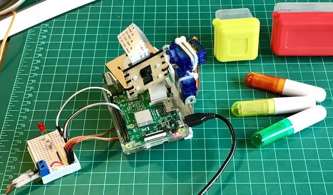
In a previous tutorial, we explored how to control a Pan/Tilt Servo device to position a PiCam (Raspberry Pi camera). This time, we will use your device to help the camera automatically track an object of a certain color, just like in the animated GIF below:
Although this is my first time using OpenCV, I must admit that I have fallen in love with this “open-source computer vision library”.
OpenCV is free for academic and commercial use. It has interfaces for C++, C, Python, and Java, and supports Windows, Linux, MacOS, iOS, and Android systems. In my OpenCV tutorial series, we will focus on using Raspberry Pi (of course, the operating system is Raspbian) and Python. OpenCV is designed for efficient computation and focuses heavily on real-time applications. Therefore, it is perfect for physical computing projects (i.e., using software and hardware that can sense and respond to the physical world to build interactive physical systems).
2. Installing OpenCV 3 Library
I am using a Raspberry Pi V3 with the latest Raspbian version (Stretch) installed. The best way to install OpenCV is to follow Adrian Rosebrock’s excellent tutorial: Raspbian Stretch: Install OpenCV 3 + Python on your Raspberry Pi.
I have tried several different OpenCV installation tutorials on my Raspberry Pi, and Adrian’s is the best one. I recommend that readers follow the steps in this tutorial step by step.
Once you finish Adrian’s tutorial, your Raspberry Pi should have the OpenCV virtual environment installed and ready for our experiments.
Let’s check the virtual environment again and confirm that OpenCV 3 has been installed correctly.
Adrian suggests running the “source” command every time you open a new terminal to ensure your system variables are set correctly:
source ~/.profile
Next, enter our virtual environment:
workon cv
If you see (cv) before your command prompt, it means you have entered the virtual environment “cv”.
(cv) pi@raspberry:~$
Adrian emphasizes that the Python virtual environment “cv” is completely independent of the Python version that comes with Raspbian Stretch. This means that the libraries in the system Python’s site-packages directory cannot be used in the virtual environment “cv”—similarly, the packages in this virtual environment cannot be used in the global Python version of the system.
Now, Python interpreter, start!
python
Please make sure you are using Python version 3.5 or higher.
In the interpreter (you should see the “>”>”> prompt), import the OpenCV library:
import cv2
If no error messages appear, it means OpenCV has been installed correctly in your virtual environment~
3. Testing Your Camera
Now that your Raspberry Pi has OpenCV installed, let’s test if your camera is working properly~ (Assuming you have installed PiCam on your Raspberry Pi)
Enter the following code in your IDE:
import numpy as np
import cv2
cap = cv2.VideoCapture(0)
while(True):    ret, frame = cap.read()    frame = cv2.flip(frame, -1) # Flip camera vertically    gray = cv2.cvtColor(frame, cv2.COLOR_BGR2GRAY)        cv2.imshow('frame', frame)    cv2.imshow('gray', gray)    if cv2.waitKey(1) & 0xFF == ord('q'):        break
cap.release()
cv2.destroyAllWindows()
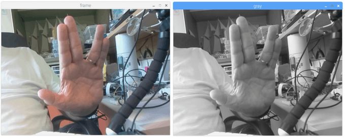
The code above will capture your PiCam’s video stream and display it using BGR color mode and grayscale mode.
Note that my camera was upside down during assembly, so I flipped the resulting image vertically. If you do not have my situation, please remove the line frame = cv2.flip(frame, -1).
Alternatively, you can directly download my code from my GitHub: simpleCamTest.py
To run my code, execute:
python simpleCamTest.py
To end the program, press the [q] key or [Ctrl]+[C] keys on your keyboard.
The following image is my result:
To learn more about OpenCV, you can refer to the following tutorial:loading -video-python-opencv-tutorial
4. Color Detection with Python and OpenCV
One thing we want to do is detect and track an object of a certain color. To do this, we must understand a bit about how OpenCV translates colors.
Regarding color detection, Henri Dang wrote an excellent tutorial: Color Detection in Python with OpenCV.
Typically, our camera works in RGB color mode. RGB color mode can be thought of as: All the colors we see can be composed of three colors of light (red, green, blue). However, OpenCV defaults to BGR color mode, which rearranges the order of RGB.
As mentioned above, using BGR color mode, each pixel can be composed of three parameters—blue, green, red. Each parameter is usually a value between 0~255 (or hexadecimal from 0x00 to 0xFF). For example, the BGR value of pure blue on a computer screen is: blue 255, green 0, red 0.
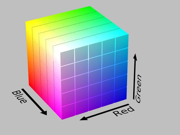
OpenCV also uses an alternative to the RGB model—the HSV (Hue, Saturation, Value) color model, which was proposed by computer graphics researchers in the 1970s to better match human visual perception of color attributes.
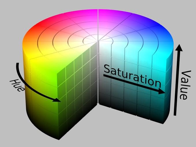
Alright. If you want to use OpenCV to track a specific color, you must define it using the HSV model.
Example
For example, I want to track the yellow plastic box in the image below. The first thing to do is find its BGR value. You can sample it in many ways (I used PowerPoint here).
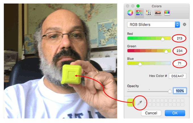
I found the following values:
-
Blue:71
-
Green:234
-
Red:213
Next, we need to convert the BGR model (71, 234, 213) to the HSV model, which will be defined in the form of upper and lower bounds. Let’s execute the following code:
import sys
import numpy as np
import cv2
blue = sys.argv[1]
green = sys.argv[2]
red = sys.argv[3]
color = np.uint8([[[blue, green, red]]])
hsv_color = cv2.cvtColor(color, cv2.COLOR_BGR2HSV)
hue = hsv_color[0][0][0]
print("Lower bound is :"),print("[" + str(hue-10) + ", 100, 100]\n")
print("Upper bound is :"),print("[" + str(hue + 10) + ", 255, 255]")
You can also download my code from GitHub: bgr_hsv_converter.py
To run my script, execute the following command and pass the BGR values as parameters:
python bgr_hsv_converter.py 71 234 213
This program will calculate the upper and lower bounds of the HSV value for our target object. Given the above parameters will yield:
lower bound: [24, 100, 100]
And
upper bound: [44, 255, 255]
The results will be displayed in the terminal.

Finally, let’s see how OpenCV selects our object based on the given color.
import cv2
import numpy as np
# Read the picture - The 1 means we want the image in BGR
img = cv2.imread('yellow_object.JPG', 1)
# resize image to 20% in each axis
img = cv2.resize(img, (0,0), fx=0.2, fy=0.2)
# convert BGR image to a HSV image
hsv = cv2.cvtColor(img, cv2.COLOR_BGR2HSV)
# NumPy to create arrays to hold lower and upper range
# The "dtype = np.uint8" means that data type is an 8 bit integer
lower_range = np.array([24, 100, 100], dtype=np.uint8)
upper_range = np.array([44, 255, 255], dtype=np.uint8)
# create a mask for image
mask = cv2.inRange(hsv, lower_range, upper_range)
# display both the mask and the image side-by-side
cv2.imshow('mask',mask)
cv2.imshow('image', img)
# wait for user to press [ ESC ]
while(1):  k = cv2.waitKey(0)  if(k == 27):    break
cv2.destroyAllWindows()
You can also download my code from GitHub: colorDetection.py
To execute my script, run the following command and pass the image name as a parameter (my image is yellow_object.JPG):
python colorDetection.py
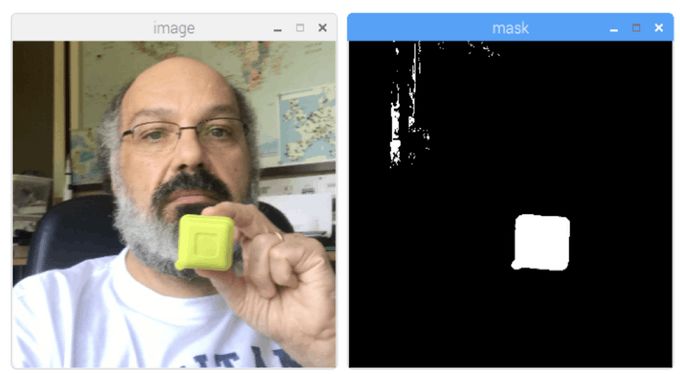
This script will display the original image (“image” window) and the mask filtered by OpenCV using the color range (“mask” window).
5. Moving Object Tracking
Now that we know how to use a mask to select our object, let’s use the camera to track its movement in real-time. To do this, I wrote my code based on Adrian Rosebrock’s OpenCV ball tracking tutorial.
I strongly recommend you read Adrian’s tutorial in detail.
First, make sure you have the imutils library installed. It is a collection of easy-to-use functions for basic image processing tasks (such as resizing, flipping, etc.) created by Adrian based on OpenCV. If you haven’t installed it yet, run the command below in your Python virtual environment:
pip install imutils
Next, download the ball_tracking.py code from my GitHub and execute it with the command below:
python ball_traking.py
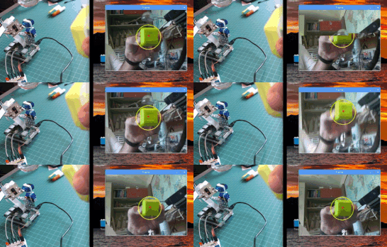
You will see results similar to the GIF below:
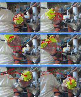
Overall, my code is not much different from Adrian’s except for the “vertical flip of the video”:
frame = imutils.rotate(frame, angle=180)
Note that the boundary values of the color mask used here are the ones we obtained in the previous step.
6. Testing General IO
Now that we have mastered the basics of OpenCV, it’s time to install an LED on the Raspberry Pi to test the general IO.
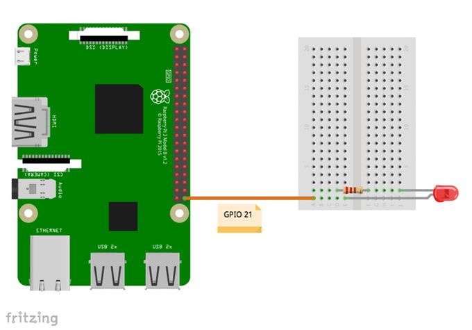
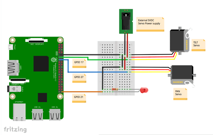
Please follow the circuit in the image above: The negative terminal of the LED connects to GPIO 21, and the positive terminal connects to a 220Ω resistor and then to GND.
Now, let’s test this LED using our Python virtual environment!
Please note that your Python virtual environment may not have the Raspberry Pi’s RPi.GPIO installed yet. If not, run the command below to install it using pip (make sure you are in the virtual environment “cv”):
pip install RPi.GPIO
Now let’s use a Python script to do a simple test:
import sys
import time
import RPi.GPIO as GPIO
# initialize GPIO and variables
redLed = int(sys.argv[1])
freq = int(sys.argv[2])
GPIO.setmode(GPIO.BCM)
GPIO.setup(redLed, GPIO.OUT)
GPIO.setwarnings(False)
print("\n [INFO] Blinking LED (5 times) connected at GPIO {0} \at every {1} second(s)".format(redLed, freq))
for i in range(5):    GPIO.output(redLed, GPIO.LOW)    time.sleep(freq)    GPIO.output(redLed, GPIO.HIGH)    time.sleep(freq)    # do a bit of cleanup
print("\n [INFO] Exiting Program and cleanup stuff \n")
GPIO.cleanup()
The code above requires a GPIO port number and an LED blinking frequency as parameters. The LED will blink 5 times before the program ends. Remember to release GPIO before exiting.
That is, when running the script, you need to provide two parameters: “LED GPIO” and frequency. For example:
python LED_simple_test.py 21 1
The command above means using the LED connected to “GPIO 21” and blinking once every second, for a total of five times.
Similarly, the above code can be downloaded from GitHub: GPIO_LED_test.py

The image above shows the result of my program. As for whether the LED lights up, you will have to verify it yourself.
Alright, let’s combine OpenCV and basic GPIO operations together~
7. Color Recognition and GPIO Interaction
Let’s start integrating OpenCV code and GPIO for interaction. We will start from the final OpenCV code and integrate the GPIO_RPI library into the code, so that when the camera detects our colored object, the red LED will stay on. This step uses code based on Adrian’s very nice tutorial OpenCV, RPi.GPIO, and GPIO Zero on the Raspberry Pi
The first thing to do is: “create” our LED object to connect to the specified GPIO.
import RPi.GPIO as GPIO
redLed = 21
GPIO.setmode(GPIO.BCM)
GPIO.setwarnings(False)
GPIO.setup(redLed, GPIO.OUT)
Second, we must initialize the LED (turn it off):
GPIO.output(redLed, GPIO.LOW)
ledOn = False
Now, in the code loop, when the object is detected, and the “circle” is created, we will turn on the LED light
GPIO.output(redLed, GPIO.HIGH)
ledOn = True
You can download the complete code from my GitHub: object_detection_LED.py
Run the code using the command:
python object_detection_LED.py
The image below shows the effect achieved. Note: When an object is detected, the LED light at the bottom left of the image will be on.
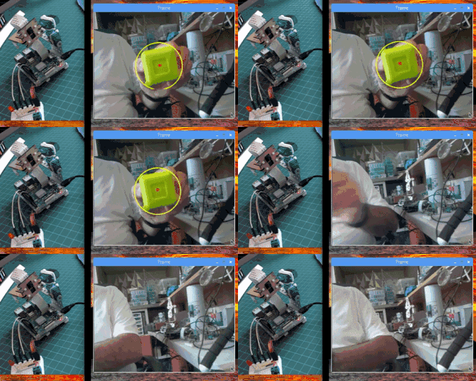
Try different colors and shapes of objects, and you will find that once the color matches the mask range, the LED light will turn on.
The video below shows some experiences. Note that only yellow objects within a certain color range will be detected, and the LED will light up. Other differently colored objects will be skipped.
As explained in the last step, we only used the LED light. However, in the video, the camera integrated with the pan-tilt mechanism (Pan Tilt: refers to the camera’s ability to move in all directions horizontally/vertically), so feel free to ignore it for now. We will implement the pan-tilt mechanism in the next step.
8. Pan-Tilt Mechanism
Now that we have the basics of OpenCV and GPIO, let’s upgrade the pan-tilt mechanism.
For more details, please check my tutorial: Pan-Tilt-Multi-Servo-Control
Servos (servo: a combination of micro-electronics and mechanical products) need to be connected to an additional 5V power supply module, and these servos connect to the GPIO of the Raspberry Pi using their data ports (here, they are the yellow wires) as follows:
-
GPIO 17 ==> Tilt Servo
-
GPIO 27 ==> Horizontal Servo
Don’t forget to connect the GND (GND: ground pin) as well ==> Raspberry Pi—Servo—Additional Power Supply Module
You have an option: To protect your Raspberry Pi in case of problems with the servos, you can connect a 1K ohm resistor in series between the Raspberry Pi GPIO and the data input pin of the servos.
Let’s take this opportunity to test our servos in the virtual Python environment. We will execute a Python script to test the driver.
from time import sleep
import RPi.GPIO as GPIO
GPIO.setmode(GPIO.BCM)
GPIO.setwarnings(False)
def setServoAngle(servo, angle):  pwm = GPIO.PWM(servo, 50)  pwm.start(8)  dutyCycle = angle / 18. + 3.  pwm.ChangeDutyCycle(dutyCycle)  sleep(0.3)  pwm.stop()
if __name__ == '__main__':
import sys  servo = int(sys.argv[1])  GPIO.setup(servo, GPIO.OUT)  setServoAngle(servo, int(sys.argv[2]))  GPIO.cleanup()
The core of the code above is the setServoAngle(servo, angle) method. This method receives parameters: A GPIO number and an angle value at which the servo is positioned. Once the angle value is input into this method, we must convert it to an equivalent duty cycle (duty cycle: the time period in which the servo changes angle).
When executing the script, you need to input two parameter values: The GPIO port corresponding to the servo and the angle value.
For example:
python angleServoCtrl.py 17 45
The command line above will position the servo connected to GPIO 17 to an “altitude” of 45 degrees.
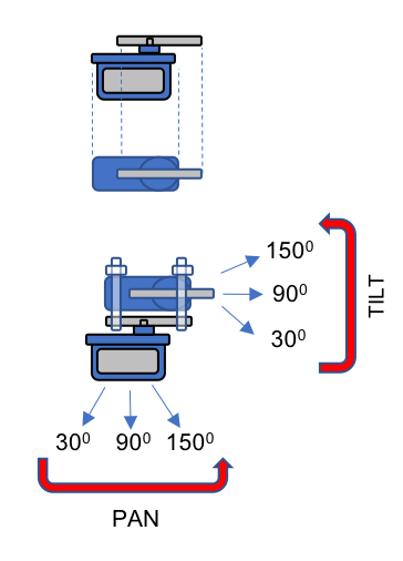
The angleServoCtrl.py file can be downloaded from my GitHub.
9. Real-time Object Positioning
The idea of positioning the object in the center of the screen will use the pan-tilt mechanism. The bad news is that we must locate the object’s position in real-time, but the good news is that if we already know the center coordinates of the object, it will be easy.
First, we will use the “object_detect_LED” code we used before, and modify it to print the detected object’s x, y coordinates.
The code can be downloaded from my GitHub: objectDetectCoord.py
The core logic of the code is: Draw a circle on the detected object’s area, and draw a red dot at the center of the circle.
# only proceed if the radius meets a minimum size
if radius > 10:  # draw the circle and centroid on the frame,  # then update the list of tracked points  cv2.circle(frame, (int(x), int(y)), int(radius),    (0, 255, 255), 2)  cv2.circle(frame, center, 5, (0, 0, 255), -1)
  # print center of circle coordinates  mapObjectPosition(int(x), int(y))
  # if the led is not already on, turn the LED on  if not ledOn:    GPIO.output(redLed, GPIO.HIGH)    ledOn = True
We output the center point coordinates to the mapObjectPosition(int(x), int(y)) method to print these coordinates. The method is as follows:
def mapObjectPosition (x, y): print ("[INFO] Object Center coordinates at \ X0 = {0} and Y0 = {1}".format(x, y))
When running this program, we will see the output of the (x,y) coordinates in the command line terminal, as shown in the image below:
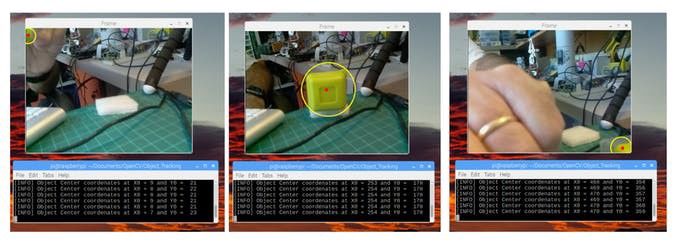
Great! We can use these coordinates as the starting point for the pan-tilt tracking system.
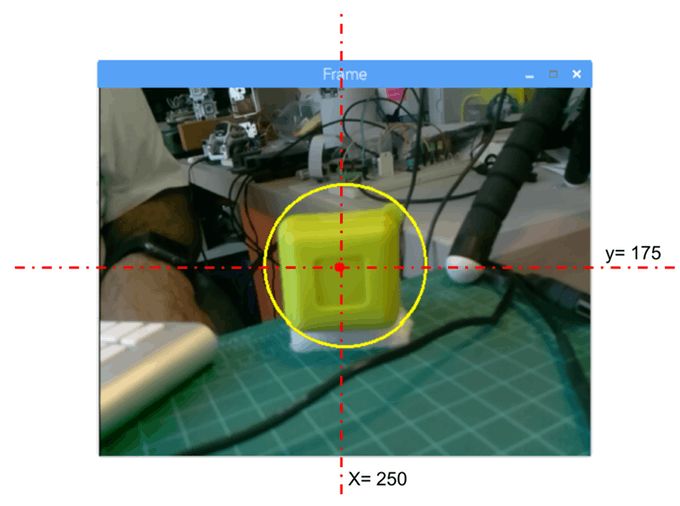
10. Object Position Tracking System
We want the target to always be in the center of the screen, so let’s define it, for example: If the following conditions are satisfied, we consider the object to be in the center:
-
220 < x < 280
-
160 < y < 210
If outside this boundary, we need to correct the deviation by moving the pan-tilt device. Based on this logic, we can construct the following method mapServoPosition(x, y). Note that the “x” and “y” used in this method are the same as the center position we printed earlier.
# position servos to present object at center of the frame
def mapServoPosition (x, y):    global panAngle    global tiltAngle    if (x < 220):        panAngle += 10        if panAngle > 140:            panAngle = 140        positionServo (panServo, panAngle)    if (x > 280):        panAngle -= 10        if panAngle < 40:            panAngle = 40        positionServo (panServo, panAngle)    if (y < 160):        tiltAngle += 10        if tiltAngle > 140:            tiltAngle = 140        positionServo (tiltServo, tiltAngle)    if (y > 210):        tiltAngle -= 10        if tiltAngle < 40:            tiltAngle = 40        positionServo (tiltServo, tiltAngle)
Based on these (x,y) coordinates, and using the method positionServo(servo, angle), the servo position command has been generated. For example: If the “y” position is “50”, it means that our object is almost at the top of the screen, meaning the camera’s view is pointing down (for example, the tilt mechanism is at 120°), so we need to lower the tilt mechanism’s angle (for example, adjust it to 100°), so the camera’s view will rise, thus moving the object down on the screen (for example, the y coordinate increases to 190).
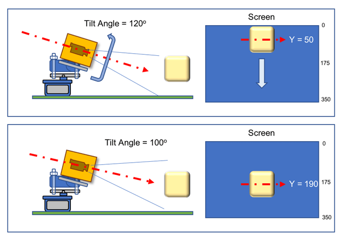
The illustration above geometrically explains the example given.
Think about how the camera moves on the horizontal device. Note that the screen is not a mirrored mapping, meaning that when you face the camera, if you move the object to “your left”, it will actually move to “your right” on the screen.
The positionServo(servo, angle) method can be written as follows:
def positionServo (servo, angle): os.system("python angleServoCtrl.py " + str(servo) + " " + str(angle)) print("[INFO] Positioning servo at GPIO {0} to {1} \ degrees\n".format(servo, angle))
In the code above, we will call the previously displayed servo movement script.
Note: angleServoCtrl.py must be in the same directory as objectDetectTrac.py.
The complete code can be downloaded from my GitHub: objectDetectTrack.py
The GIF below shows the effect of our project running:

11. Conclusion
I hope this project can help others find their way into the exciting world of electronics.
For project details and the final code, you can browse my GitHub repository: OpenCV-Object-Face-Tracking.
For more projects, please visit my blog: MJRoBot.org
Below is a preview of my next tutorial, where we will explore “Face Tracking and Detection”.
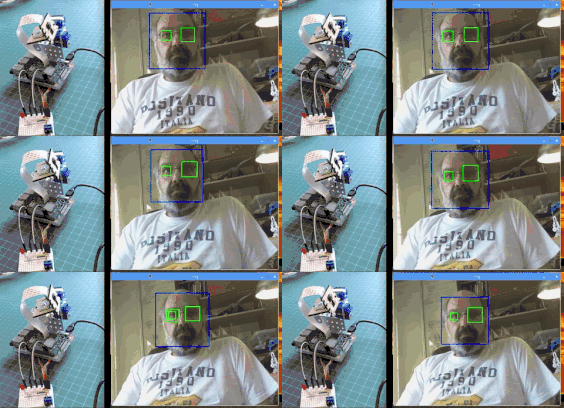
Greetings from the southern hemisphere!
See you in the next article!
For related reference content and links, please click Read the original text to visit and view.
via https://towardsdatascience.com/automatic-vision-object-tracking-347af1cc8a3b

Efficiently docking AI field project cooperation, consulting services, internships, job hunting, recruitment and other needs, backed by 250,000 public account fans, looking forward to connecting with you, making it easier to find people and technology!
Group Chat
Welcome to join the public account reader group to exchange with peers. Currently, there are SLAM, algorithm competitions, image detection segmentation, face and body, medical imaging, computational photography, autonomous driving, and other comprehensive WeChat groups (which will be gradually subdivided in the future). Please scan the WeChat account below to join the group, and note: “nickname + school/company + research direction”, for example: “Zhang San + Shanghai Jiao Tong University + Visual SLAM”. Please follow the format, otherwise it will not be approved. After successfully adding, you will be invited to enter the relevant WeChat group based on your research direction. Please do not send advertisements in the group, otherwise you will be removed from the group. Thank you for your understanding~

Recommended Reading
Practice | Camera Calibration
Practice | Image Correction Technology
Practice | The crystallization of ARKit and OpenCV under Unity
Practice | Remote sensing image semantic segmentation based on SegNet and U-Net
Practice | Text Localization and Cutting
Practice | Source Code Entry to Faster RCNN
Practice | I implemented a scanner by myself
I used MATLAB to implement a 2D LiDAR SLAM
Practice | What moment made you suddenly feel that CV technology is really useful?
Dry Goods | The most comprehensive OpenCV live detection tutorial in history
Solution | How to accurately measure the volume of an object with a regular mobile phone?
Implementation of custom object (drone) detection using Mask-RCNN model
Introduction to image processing with scikit-image
Are you still using the naked eye to find differences? This technology easily solves it
Skills to measure the size of objects with OpenCV~
Latest AI dry goods, I am watching 